Samson Controls Pty Ltd |
|
| Street name: | U13-15/61-71 Beauchamp Road |
| Suburb: | Matraville |
| State: | NSW |
| Post Code: | 2036 |
| Postal Address: | As above |
| Sydney | Melbourne | Perth | Brisbane | |
| Phone: | 61 (0)2 9316 7800 | 03 9645 7393 | 08 9248 7686 | 0755946705 |
| Fax: | 61 2 9666 5963 | 03 9645 7394 | 08 9248 7689 | 0755946255 |
Contact Names
| Managing Director: | Mr Jacky van Wolput | |
| Sales Department: | Sydney: |
|
| Brisbane | Mr Gerard Foran | |
| Melbourne: |
|
|
| Perth: |
|
|
| Spare Parts/Customer Service: | Ms Helen Hannoun | |
| Email: | ||
| Web Site: | http://www.samson.de/esamson.htm | |
Samson Controls operates as a subsidiary of Samson AG of Germany, who is recognised as being leaders in the field of Control Valve technology. They are one of the top 5 leading suppliers in the Chemical Industry worldwide and in the top 5 suppliers of Control Valves worldwide.
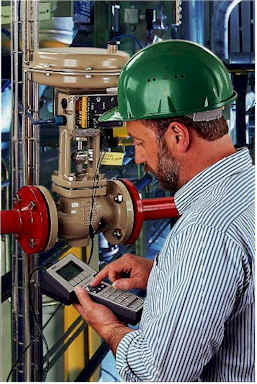
Samson manufactures Industrial Control Valves, Self-Operated Regulating Valves and an extensive range of process instrumentation, especially Valve management accessories.
Focussed to meet all of the technical and quality requirements of the petrochemical, mining, petroleum, food & beverage, chemical, pulp & paper, oil & gas and sugar industries, Samson manufacture their Valves to the highest possible quality standards being authorised by the German TUV. This Authorisation confirms that Samson provides facilities, which allow for the proper manufacture, inspection and testing of products according to the latest technical standards.
Samson is accredited to the Quality Assurance Standard of ISO 9001.
The intense commitment and high level of investment into Research and Development, has resulted in Samson Control Valves possessing an extremely modular and compact construction, bearing significantly reduced weight and height when compared to other globe valve designs.
Samson have a wide manufacturing programme, which encompasses two-way, three-way and angle globe valves, high performance butterfly, eccentric disc/ball and PTFE lined control valves, positioning Samson with the ability to offer the right control valve solution for every application.
Specialising in Valves for chemical applications, erosive service, noise and cavitation control, Samson control valves can be equipped with low noise cages and hardened metal or ceramic trims. Special trim materials, such as Tool Steel WN1.4112 and Ceramics have been successfully employed in erosive and cavitating/flashing media, providing significantly increased life over standard trim materials.
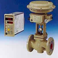
Excellent rangeability of 50:1 is achieved through the use of a special low-noise, characterised V-Ported Plug (designed to provide longer life in cavitating applications too), and the wide interchangeability of trim sizes (with up to 22 Cv values per valve size). By a simple exchange of the plug and seat, optimum control performance within any body size can be achieved.
Special steam conditioning valves provide simultaneous pressure and temperature reduction, within a single Valve body. The Type 281/284 valve body designs provide outstanding turndown (50:1), low-noise, low-vibration operation and excellent atomisation, over a wide range of flows.
All Samson control valves can be equipped with multi-spring diaphragm actuators, which may be operated by air, gas or hydraulic fluid including water), electro-hydraulic actuators or electric actuators. The diaphragm actuators are available with epoxy-coated Steel or 316 Stainless Steel enclosures, being especially developed for use in offshore/mining applications.
Our actuators can also be equipped with a ‘fire-safe’ capsule the render them ‘Firesafe’. They are designed to remain tightly closed/open in the event of a fire, for up to 8 hours.
In addition to control valves, Samson manufacture a high performance range of pneumatic, analog, and smart positioners. Optionally equipped with an interface abiding to HART, Profibus or Fieldbus Foundation protocols, these Smart Positioners use standardised mounting kits for attachment to all types of rotary and linear control valves. Samson DVCs provide an auto-calibration function, enable parameter establishment and have comprehensive monitoring and diagnostic features, with information being accessed locally or remotely as preferred.
Samson positioners are certified intrinsically safe, approved to Australian Standard EEx ia n IIC T6 - for use in hazardous and explosion-proof areas. A full range of Valve accessories are available, including I/P converters (with up to 8 Bar output), air filter regulators, lock-up valves and speed control devices (with 316SS housing options).
Furthermore, as a complement to the Control Valve range, Samson manufacture a wide range of self-operated regulating valves from ½" to 20" NB for steam, gas and liquid applications. These valves require no auxiliary energy, are very accurate and are also of a modular construction, available with a wide range of low noise trims. They are easy to assemble and service, and greater safety can be achieved as they continue to work reliably in the event of power failure. Designs are available for pressure, temperature, and differential pressure and flow control with optional electric override and safety shut-down features.
Samson Controls offers full technical sizing, application support and can assist with custom designed Valves for special applications. Our sizing programme which may be used to size all types of control valves, incorporates four different Noise Calculation methods, including the new International IEC Standard 534-8-3, plus a special Samson calculation method, based upon over 3,000 actual performance tests. Please contact us for information, or if you wish to purchase a copy.
If you have an enquiry, or would like any further information on our products, please contact us, or see us on the Web at http://www.samson.de
Using Instrumented Systems for Overpressure Protection
By Dr. Angela E. Summers, PE
SIS-TECH Solutions, LLC - Houston, TX
Prepared for Presentation at the 34 th Annual Loss Prevention Symposium, March 6-8, 2000 Overpressure Protection Alternative Session
Copyright © SIS-TECH Solutions, LLC, December 1999
Accepted for publication in Chemical Engineering Progress
AICHE shall not be responsible for statements or opinions contained in papers or printed publications.
Abstract
Industry is moving towards the use of high integrity protection systems (HIPS) to reduce flare loading and alleviate the need to upgrade existing flare systems when expanding facilities. The use of HIPS can minimize capital project costs, while meeting an evolving array of standards and regulations. This paper will discuss API and ASME standards and how these relate to ANSI/ISA S84.01-1996 and IEC 61508. It will focus on process that should be followed in implementing the engineering design of HIPS.
Introduction
In the process industry, a key safety consideration is the control and response to over-pressure situations. Industry standards from the American Petroleum Institute (API) and American Society of Mechanical Engineers (ASME) provide criteria for the design of vessels and the protection of these vessels from over-pressure. Traditionally, pressure relief valves and flares were used to handle the relieving of vessels in the worst credible scenario. Flare loading calculations gave no credit for operator intervention, fail safe equipment operation or trip systems. But times have changed. In many communities and countries around the world, the belt is tightening on the venting and combustion of gases. It is simply not acceptable to flare large volumes of gas. In addition, the cost of designing and installing large flare systems has continued to rise. API 521 (1) andCase 2211 of ASME Section VIII, Division 1 and 2 (2), provide alternatives in the design of overpressure protection systems. These alternatives revolve around the use of an instrumented system that exceeds the protection provided by a pressure relief valve and flare system.
These instrumented systems are safety-related systems, since their failure can result in the vessel rupture or in overloading the flare. As safety-related systems, they must be designed according to either the United States domestic ANSI/ISA S84.01-1996 (3) or the international standard draft IEC 61508 (4,5). The risk typically involved with overpressure protection results in the need for high safety system availability; therefore, these systems are often called "high integrity protection systems" or HIPS.
Regulations and Standards Concerning HIPS
API and ASME provide design standards for pressure vessels. These design standards are used worldwide by insurers to determine the appropriateness of pressure vessel design. As industry-recognized institutions, many API and ASME standards, are enforceable in the United States under OSHA PSM 7 and EPA RMP 8 . In many other countries worldwide, these standards are enforceable under local and/or national regulations.
ANSI/ISA S84.01-1996 and draft IEC 61508 are standards for SIS design. As a US industrial standard, ANSI/ISA S84.01-1996 is also enforceable as good engineering practice under OSHA PSM (6) and EPA RMP (7). When finalized, draft IEC 61508 will be accepted in many countries as an enforceable national standard, whether associated with a national regulation or independently mandated.
American Petroleum Institute (API)
API has recommended practices that address pressure relieving and depressuring systems in the petroleum production industry. API 521 describes flare system design methods. These methods basically require sizing the relief valve for each vessel for the worst credible scenario and require sizing the main flare header for the worst case relieving scenario, involving the simultaneous venting of all affected vessels. The fourth edition of API 521 allows credit to be taken for a favorable response of some of the instrument systems. While this design alternative is provided, API 521 Part 2.2 recommends the use of high integrity protective systems (HIPS) only when the use of pressure relief devices is impractical.
American Society of Mechanical Engineers (ASME)
ASME Code Case 2211, approved in 1996, sets the conditions under which over-pressure protection may be provided by an instrumented system instead of a PRV. This ruling is intended to enhance the overall safety and environmental performance of a facility by utilizing the most appropriate engineered option for pressure protection. While there are no specific performance criteria in the Case Code, the substitution of the HIPS for the PRV should provide a safer installation. Consequently, the substitution is generally intended for limited services where the PRV may not work properly due to process condition, e.g. plugging, multiple phases, etc. The overpressure protection can be provided by a SIS in lieu of a pressure relieving device under the following conditions:
- The vessel is not exclusively in air, water, or steam service.
- The decision to utilize overpressure protection of a vessel by system design is the responsibility of the User.
- The User must ensure the MAWP of the vessel is higher than the highest pressure that can reasonably be expected to be encountered by the system.
- A quantitative or qualitative risk analysis of the proposed system must be made addressing all credible overpressure scenarios.
- The analysis in (c) and (d) must be documented.
International Society for Measurement and Control (ISA) and International Electrotechnical Commission (IEC) :
ANSI/ISA S84.01-1996 and draft IEC 61508 are intended to address the application of safety instrumented systems (SIS) for the process industries. The objective of these standards is to define the design and documentation requirements for SIS. While these design standards are not prescriptive in nature, the design processes mandated in these standards cover all aspects of design including: risk assessment, conceptual design, detailed design, operation, maintenance, and testing (8). To ensure compliant implementation, the requirements of these standards, as pertaining to a specific HIPS application, must be investigated thoroughly.
One of the most important criteria for SIS design is the requirement that the User assign and verify the safety integrity level (SIL) for the SIS (9). The assignment of SIL is a corporate decision based on risk management philosophy and risk tolerance. Safety instrumented systems (SIS) should be designed to meet a safety integrity level, which is appropriate for the degree of hazard associated with the process upset. Safety integrity levels per draft IEC 61508, and ANSI/ISA S84.01 are designated in the following table.
Table 1: Safety Integrity Levels
| Safety Integrity Level | Availability Required | Probability to Fail on Demand | 1/PFD | ||
| IEC 61508 |
4 | >99.99% | E-005 to E-004 | 100,000 to 10,000 | |
| ISA S84 |
3 | 99.90-99.99% | E-004 to E-003 | 10,000 to 1,000 | |
| 2 | 99.00 - 99.90% | E-003 to E-002 | 1,000 to 100 | ||
| 1 | 90.00 - 99.00% | E-002 to E-001 | 100 to 10 | ||
From the point of SIL selection, the entire lifecycle of the SIS is evaluated for agreement with the SIL. Thus, the SIL is the cornerstone of the SIS design.
Advantages and Disadvantages of Using HIPS
Industry is increasingly moving towards utilizing HIPS to reduce flare loading. They are becoming the option of choice to help alleviate the need to replace major portions of the flare system in existing facilities when adding new equipment or units. If the header and flare system must be enlarged, significant downtime is incurred for all of the units that discharge to that header. The relatively low capital cost of HIPS compared to flare system piping upgrades and the ability to install HIPS without incurring significant additional downtime during a turnaround, makes these systems an extremely attractive option. Another benefit is that the process unit will not flare as much as a process unit designed for full flare loading. In some areas of the world, this is becoming important as regulatory agencies place greater restrictions on flaring.
The main disadvantage of HIPS is these systems are more complex and require that many different components work as designed. The effectiveness of the system is highly dependent on the field design, device testing, and maintenance program. The ability of the HIPS to adequately address overpressure is limited by the knowledge and skill applied in the identification and definition of overpressure scenarios. When a PRV is not installed, the HIPS becomes the "last line of defense," whose failure potentially results in rupture of the vessel or pipeline.
Making the Decision to Use HIPS
A decision tree can be utilized to facilitate the use of HIPS in the process industry. Figure 1 is a highly simplified decision tree showing only the key steps in assessing and designing a HIPS.
Figure 1. Simplified Decision tree
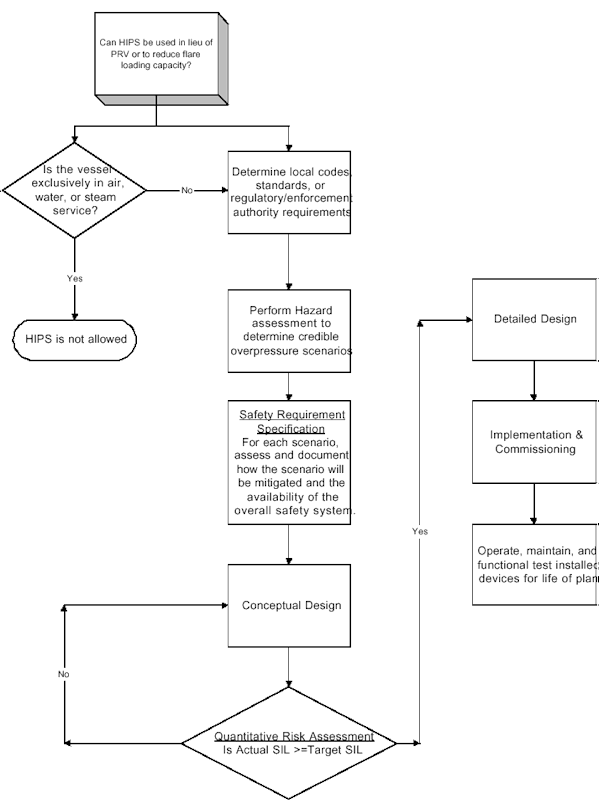
The first question that must be asked revolves around regulatory and standards issues. Some local codes mandate the use of PRVs, regardless of the industry standards, so make sure local jurisdictional issues are understood. From ASME Code Case 2211, the vessel can not be exclusively in air, water, or steam service. This requirement is intended to prevent building utility systems (e.g. residential boilers) from being installed without PRVs.
Once the local regulations and standards are understood, a hazard assessment must be performed to determine the credible overpressure scenarios. During the hazard assessment, analyze each scenario thoroughly. If any scenario is determined to be non-credible during the assessment, make sure the documentation provides adequate justification. Remember that the flare system most likely will not be to handle your non-credible event, if it turns out to be credible and happens.
A safety requirement specification (SRS) should be developed to address various overpressure scenarios. The SRS will describe the specific actions required to mitigate each scenario. When assessing the performance of HIPS, examine the process dynamics carefully to make sure that the instrumented system can respond fast enough to the event to prevent the overpressure of the vessel. In addition to the safety functional requirements, the SRS also includes the documentation of the safety integrity requirements, including the safety integrity level (SIL) and anticipated testing frequency.
Typically, the high availability requirements for HIPS drive the choices made concerning component integrity, component redundancy, common cause concerns, diagnostic requirements, and testing frequency. The conceptual design or basis of design document must specify exactly how the HIPS will be configured to achieve the necessary availability.
For documentation of the "as safe or safer" and compliance with the target SIL, the design of any HIPS should be quantitatively verified to ensure it meets the required availability. Quantitative verification of SIL for HIPS is the generally accepted approach for most companies utilizing HIPS. This is because the quantitative technique is the most defensible from a legal standpoint. A draft guidance report by ISA, ISA dTR84.02 (10, 11, 12, 13, 14), recommends use of one of the following methods for SIL Verification:
- Markov Models
- Fault Tree Analysis (FTA)
- Simplified Methods
Any of these techniques can be utilized to determine whether the design meets therequired SIL. If it does not meet the required SIL, the design must be modified until it does.
Detailed design and implementation/commissioning activities must be performed within the bounds of the safety requirements specification and the conceptual design. Any deviations from these documents must be evaluated for impact on the safety integrity level and on any assumptions made with regard to performance.
Finally, the HIPS must be operated, maintained and tested throughout the life of the plant. The high integrity of HIPS is often achieved through the use of frequent testing. Once the required testing frequency is documented in the SRS, it must be done. If the SRS says that the testing occurs at a 6 month interval, it must be done at 6 months, not one year.
Conclusions
Care must be taken in any decision to implement HIPS. The use of HIPS should be generally restricted to the reduction of relief and flare loading in existing facilities. The use of an instrumented system should not be used as the only justification for reducing the pressure relieving requirements on individual pieces of equipment. Any justification should be thoroughly documented through a hazard analysis, which identifies all potential overpressure scenarios and consequences of the scenarios. A SIL appropriate to the risk should be selected and the design should be validated for adherence to this SIL.
All of the regulatory and standards issues boil down to a few simple rules:
- Specific regulatory and enforcement jurisdiction requirements must be determined. In some instances, approval of local authorities is required.
- Regulatory and standards requirements must be understood by all parties, including management, I&E, operations, and maintenance.
- Detailed hazard assessment must be performed to demonstrate that the HIPS solution can adequately address all credible overpressure scenarios.
- The User must verify that HIPS will work from a process standpoint (i.e., Can the valves shut in time to prevent pressure wave propagation?).
- The availability of the HIPS must be as good or better than the availability of the "passive" mechanical device it replaces.
- The User must understand the importance of application-specific design aspects, as well as the associated costs of the intensive testing and maintenance program whenever a HIPS is utilized.
- Finally, there is no "approved" rubber stamp in any regulation or standard for the use of HIPS for replacement of relief devices on pressure vessels or pipelines. Substantial cautionary statements are made in all of the regulations and standards, concerning the use of HIPS. No matter what documentation is created, the User still has the responsibility to provide a safe and environmentally friendly operation.
References
- "Guide for Pressure-Relieving and Depressurizing Systems," API 521, Fourth Edition, American Petroleum Institute, March 1997.
- "Pressure Vessels with Overpressure Protection by System Design," Section VIII, Divisions 1 and 2, ASME Code Case 2211, The 1995 Boiler Pressure Vessel Code, American Society of Mechanical Engineers, 1995.
- "Application of Safety Instrumented Systems for the Process Industries," ANSI/ISA-S84.01- 1996, ISA, Research Triangle Park, NC, 1996.
- IEC 61508, 65A/255/CDV, "Functional safety of electrical/ electronic/ programmable electronic safety related systems," Parts 1, 3, 4, and 5, International Electrotechnical Commission, Final Standard, December 1998.
- IEC 61508, 65A/255/CDV, "Functional safety of electrical/ electronic/ programmable electronic safety related systems," Parts 2, 6, and 7, International Electrotechnical Commission, Final Draft International Standard, January 1999.
- "Process Safety Management of Highly Hazardous Chemicals; Explosives and Blasting Agents," 29 CFR Part 1910, OSHA, Washington, 1992.
- "Risk Management Programs for Chemical Accidental Release Prevention," 40 CFR Part 68, EPA, Washington, 1996.
- Ford, K.A. and Summers, A.E., "Are Your Instrumented Safety Systems up to Standard?," Chemical Engineering Progress, 94, pp. 55-58, November, 1998.
- Summers, A.E., "Techniques for assigning a target safety integrity level," ISA Transactions, 37, pp. 95-104 1998.
- "Safety Instrumented Systems (SIS) - Safety Integrity Level (SIL) Evaluation Techniques, Part 1: Introduction," TR84.0.02, Draft, Version 4, March 1998.
- "Safety Instrumented Systems (SIS) - Safety Integrity Level (SIL) Evaluation Techniques, Part 2: Determining the SIL of a SIS via Simplified Equations," TR84.0.02, Draft, Version 4, March 1998.
- "Safety Instrumented Systems (SIS) - Safety Integrity Level (SIL) Evaluation Techniques, Part 3: Determining the SIL of a SIS via Fault Tree Analysis," TR84.0.02, Draft, Version 3, March 1998.
- "Safety Instrumented Systems (SIS) - Safety Integrity Level (SIL) Evaluation Techniques, Part 4: Determining the SIL of a SIS via Markov Analysis," TR84.0.02, Draft, Version 4, March 1998.
- "Safety Instrumented Systems (SIS) - Safety Integrity Level (SIL) Evaluation Techniques, Part 5: Determining the PFD of SIS Logic Solvers via Markov Analysis," TR84.0.02, Draft, Version 4, April 1998.
Biography
Dr. Angela Summers is President of SIS-TECH Solutions, LLC, specializing in safety instrumented system assessment and design. Angela contributed extensively to the development of ISA TR84.0.02, a guidance document on verifying safety integrity levels for SISs. Angela has also contributed to the development of the dIEC 61511 standard through involvement with the ISA S84 committee. Angela has taught courses on SIS assessment, evaluation and design to over 1500 process industry representatives worldwide. She has traveled extensively presenting papers at numerous technical conferences and has published papers in major trade journals.
Angela Summers has a Ph.D. in Chemical Engineering from The University of Alabama and a Masters of Engineering in Environmental Systems Engineering from Clemson University. She is a registered Professional Engineer in the State of Texas and an Adjunct Professor at the University of Houston-Clear Lake. Angela is a member of the International Society for Measurement and Control and is a member of the American Institute of Chemical Engineers.
Viewpoint on ISA TR84.0.02 – Simplified Methods and Fault Tree Analysis
Angela E. Summers, Ph.D., P.E.
President, SIS-TECH Solutions, LLC
PMB-295, 2323 Clear Lake City Blvd Houston, Texas 77062-8032
713-320-4777 (phone)
§ 281-461-8109 (fax) www.SIS-TECH.com
Accepted for publication in ISA Transactions
Abstract
ANSI/ISA-S84.01-1996 and IEC 61508 require the establishment of a safety integrity level for any safety instrumented system or safety related system used to mitigate risk. Each stage of design, operation, maintenance, and testing is judged against this safety integrity level. Quantitative techniques can be used to verify whether the safety integrity level is met. ISA-dTR84.0.02 is a technical report under development by ISA, which discusses how to apply quantitative analysis techniques to safety instrumented systems. This paper discusses two of those techniques: 1) simplified equations and 2)fault tree analysis.
Introduction
In 1996, ISA, the international society for measurement and control, voted unanimously for the approval of ISA-S84.01. In 1997, the standard was accepted by the American National Standards Institute (ANSI) and is now known as ANSI/ISA-S84.01-1996 (1). This standard is considered by the U.S. Environmental Protection Agency (EPA) and Occupational Safety and Health Administration (OSHA) as a generally accepted good industry practice (2,3). Any U.S. based instrumented systems specified after March 1997 should be designed in compliance with this standard.
Internationally, IEC 61508, "Functional Safety of Electronical/Electronic/Programmable Electronic (E/E/PES) Safety-Related Systems," (4,5) is getting very close to being released as a final standard. The standard consists of seven parts, four of which have already been issued as final and three are waiting for final vote on the final draft international standard. The intent is to release the entire standard as final in early 2000. Instrumented systems designed in the next millennium must comply with this standard with the exception of U.S. installations that must follow ANSI/ISA-S84.01-1996.
Both standards are performance-based and contain very few prescriptive requirements. The "performance" of the safety instrumented system (SIS) is based on a target safety integrity level (SIL) that is defined during the safety requirements specification development (6). According to thestandards, the ability of the SIS to achieve a specific SIL must be validated at each stage of design and prior to any change made to the design after commissioning. The entire operation, testing, and maintenance procedures and practices are also judged for agreement with the target SIL. Thus, the successful implementation of a validation process for SIL is very important for compliance with either standard.
The SP84 committee is working to complete a technical report, ISA-dTR84.0.02, which will discuss three techniques for the quantification of SIL. These methods are Simplified Equations (8), Fault Tree Analysis (9), and Markov Modeling (11). The technical report introductory material states that the purpose of dTR84.0.02 is to provide supplemental information that would assist the User in evaluating the capability of any given SIS design to achieve its required SIL and to reinforce the concept of the performance based evaluation of SIS. The technical report further states that the quantification of the SIL is performed to ensure that the SIS meets the SIL required for each safety function, to understand the interactions of all the safety functions, and to understand the impact of failure of each component in the SIS. Therefore, the technical report emphasizes the importance of evaluating the SIS design (7).
The technical report also acknowledges the importance of spurious trip rate to the operation of the facility. Spurious trips are often not without incident. There is a process disruption; alarms sound; and PRVs lift causing flares many meters high. Consequently, the technical report presents the mathematics involved in determining the spurious trip rate. When viewing the calculations presented and interpreting the results, it is important to understand that the spurious trip rate is a frequency with the units of failures per unit of time and the SIL is a probability, i.e., a dimensionless number.
ISA-dTR84.0.02 presents three quantitative methods: 1) Simplified Equations, 2) Fault Tree Analysis, and 3) Markov modeling. The technical report is not a comprehensive textbook or treatise on any of the methods. All of the parts assume that the User of the technical report has a basic understanding of probabilistic theory and the method being presented. It also assumes that the User knows how to obtain and evaluate the appropriateness of the data for a specific application. The intent of the technical report is to provide guidance on how to apply this knowledge to safety instrumented systems.
Many Users will choose to use Simplified Equations for an initial estimation of the PFDavg for various design options. It may also be used to evaluate SIL 1 and SIL 2 systems where the architecture is sufficiently simple for the hand calculations. For SIL 3 systems, the complexity of the design often makes the Simplified Equations not so simple to use. Therefore, the technical report recommends the use of Simplified Equations for "simple SISs."
For more complex SISs, Fault Tree Analysis or Markov modeling is recommended. Fault Tree Analysis is widely used by the general risk assessment industry for defining the frequency or probability of particular incident scenarios. The calculations can be done by hand, but since computer software models are readily available, most Fault Tree Analysis is performed using a computer program.
Many risk analysts are not familiar with Markov modeling and the fundamental math behind the method will be a rude awakening to those Users who have forgotten how to do matrix math or how to solve Laplace Transforms. However, Markov modeling should be used for the evaluation of any programmable logic solver (11), since Markov modeling can take into account time dependent failures and variable repair rates found in most TUV Class 5 and 6 certified logic solvers. It is best to leave the Markov modeling to the Vendor and ask the Vendor for the PFDavg at the anticipated logic solver testing frequency. Users should focus instead on learning how to apply Simplified Equations and Fault Tree Analysis to evaluate the field design, including the input and output devices and support systems.
Determining SIL of a SIS via Simplified Equations (8)
The Simplified Equation technique involves determining the PFDavg for the field sensors (FS), logic solver (LS), final elements (FE), and support systems (SS). The field sensors are the inputs required to detect the hazardous condition. The logic solver accepts these inputs and generates correct outputs that change the state of the final elements in order to mitigate the hazardous condition. The support systems are those systems that are required for successful functioning of the SIS. If the valves are air-to- move, the instrument air supply must be analyzed. If the SIS is energize-to-trip, the power supply must be considered as part of the SIS. Once the individual PFDs for each input, logic solver, output and support system are known, these PFDs are summed for the PFDSIS.
![]()
The Simplified Equations used for calculating the PFDavg were initially derived from Markov Models, however the simplification of the models resulted in some limitations. Unlike Markov Models, this method does not handle time dependent failures or sequence dependent failures. Due to these limitations, this method should not be used to analyze programmable logic solvers.
Part 2 includes equations for 1oo1, 1oo2, 1oo3, 2oo2, 2oo3, and 2oo4 architectures. These equations have been derived from Markov models, assuming the rare event approximation. The rare event approximation can only be used when the failure rate (l) multiplied by the testing interval (TI) is much smaller than 0.1. This can be stated mathematically as lTI << 0.1. Simplified Equations results in the calculation of the PFDavg for each voting configuration. The extended equations do include some variables for which published data is not available. These variables must be estimated from experience. Consequently, an experienced risk analyst and/or engineer is required for correct estimation of these variables. For instance, the equation for 1oo2 architecture is as follows:

The first term is the undetected dangerous failure of the SIS. It shows the effect that the device undetected dangerous failure rate (lDU ) and testing interval (TI) have on the PFDavg. This is the term of the most important part of this equation in determining the unavailability of the SIS. This term is actually simplified from the full Markov solution.
In explanation, the beta (b) factor method is a technique that can be used to estimate common cause failure effects on the SIS design. The b factor is estimated as a percentage of the failure rate of one of the devices in a redundant configuration, assuming both devices have the same failure rate (note third term above). Therefore, the common cause failure rate or dependent failure rate would be b*lDU and the device failure rate or independent failure rate would be (1-b)* lDU. For the purposes of Part 2, (1-b) was considered to be equal to 1, yielding conservative results. For large b factors, (1-b) should be considered, which would yield the following equation for a 1oo2 architecture:

The published data in OREDA (12), CCPS (13), and RAC (14) sometimes provide the undetected dangerous failure rate; however, many times, only a total dangerous failure rate is published. If only the total dangerous failures are known, the User must make an assumption concerning the percentage of the total dangerous failures that can be detected with diagnostics. If the percentage is not known, the total dangerous failures can be used to obtain a conservative estimate of the PFDavg.
The second term is the probability of having a second undetected failure (l DU ) during the repair of a detected failure (l DD ). This numerical value of this term is generally very small, since the repair time (MTTR) is typically less than 24 hours. Consequently, this term often can be considered negligible.
The third term represents the probability of common cause failure based on the beta factor method. The beta factor must be estimated by the User, since there is almost no published data available for current technology. The technical report states that the value is somewhere between 0 and 20%. Many Users have determined that with proper design practices (15) that a beta factor in the range of 0.1 to 2% can be used. The beta factor has a profound effect on the PFDavg obtained for redundant architectures, so it must be selected carefully. For initial comparisons of architecture and testing frequency, it is best to assume that this term is negligible. Effective design can minimize common cause failure. However, if an analysis of the design indicates that common cause failures can occur, such as shared process taps or a shared orifice plate, a beta factor should be selected and included in the final calculation.
The fourth term is the probability of systematic failure. Systematic failures are those failures that result due to design and implementation errors. Systematic failures are not related to the hardware failure. Examples of systematic failures are as follows:
- SIS design errors
- Hardware implementation errors
- Software errors
- Human interaction errors
- Hardware design errors
- Modification errors
The systematic failure rate (l DF) is extremely difficult to estimate. Also, many of the listed systematic failures will affect all of the architectures equally. If software design is poor, it does not matter whether there is one, two or three transmitters. This term also assumes that the systematic failures can be diagnosed through testing. Therefore, effective design, independent reviews, and thorough testing processes must be implemented to minimize the probability of systematic failures. When good engineering design practices are utilized, these failures can be considered negligible.
Based on the repair time being short and on the common cause and systematic failures being minimized through good design practices, these terms can be neglected yielding the following equation:

Similar reduced equations are provided for 1oo1, 1oo2, 1oo3, 2oo2, 2oo3, and 2oo4 architectures.
Determining Spurious Trip Rate via Simplified Equations
For the spurious trip rate, the full equation for 1oo2 is as follows:
![]()
The first term contains the failures associated with a device experiencing either a dangerous detected failure which forces the logic to the trip state or a safe failure. Due to spurious trip concerns, many Users choose to fail a detected device failure "away" from the trip. This converts the logic to 1oo1 for the remaining device until repair is initiated. If this type of logic is utilized, the dangerous detected failure rate contribution to the spurious failure rate can be assumed to be zero.
The second term is the common cause term and the third term is the systematic failure rate. Effective design and good engineering techniques should minimize both of these terms. The equation can then be reduced to the following:
![]()
Similar reduced equations can be derived for the other architectures.
When STR is known for each combination of field sensors, logic solver, final element, and support systems. The overall STR is calculated by summing the individual STRs. The final answer is the frequency at which the SIS is expected to experience a spurious trip.
Limitations of The Simplified Equations Methodology
The published equations in ISA-dTR84.0.02 do not allow the modeling of diverse technologies. The sensors or final elements used in each voting strategy must have the same failure rate. Consequently, this method does not allow the modeling of a switch and a transmitter or a control valve and a block valve. During the derivation for the equations in Part 2 and those shown in Part 5, it was assumed that the failure rate of voted devices were the same. It must be emphasized that this is a limitation of the equations presented in these parts. It is not a limitation of the mathematics of the methodology.
However, a significant limitation of the mathematics is the requirement that the testing frequency be the same for all voted devices. To perform the Markov model derivation, the integration is performed over the range of time 0 to time "testing frequency." Consequently all devices in a voted set must be tested at the same interval.
The method also does not allow the modeling of any SIS device interactions or complex failure logic, such as 1oo2 temperature sensors detecting the same potential event as 2oo3 pressure sensors. The actual failure logic may be that the event will not occur unless both temperature sensors and 2oo3 pressure sensors fail. This method will only look at the sensor failures as separate issues. Consequently, this method is used to model simple SISs only. However, the math is easy and all this method requires for execution is a pad of paper and a pen (or computer).
Determining SIL of a SIS via Fault Tree Analysis (9)
Part 3 discusses the use of fault trees analysis for modeling the SIS. Fault tree symbols are used to show the failure logic of the SIS. The graphical technique of Fault Tree Analysis allows easy visualization of failure paths. Since the actual failure logic is modeled, diverse technologies, complex voting strategies, and interdependent relationships can be evaluated. However, Fault Tree Analysis is not readily adaptable to SISs that have time dependent failures. As with Simplified Equations, Fault Tree Analysis is not recommended for modeling programmable logic solvers. The User should obtain the PFDavg for the logic solver from the Vendor at the anticipated logic solver testing frequency.
Fault Tree Analysis is one of the most common techniques applied for quantifying risk in the process industry. Computer programs, books, and courses are available to the User to learn how to apply Fault Tree Analysis. The technical report recommends the use of Fault Tree Analysis in SIL 2 and SIL 3 SIS applications. It does require more training and experience than the Simplified Equations, but will yield more precise results.
The mathematical approach for Fault Tree Analysis is different from Markov model analysis. Fault Tree Analysis assumes that the failures of redundant devices are independent and unconditional. In Fault Tree Analysis, the PFDavg is calculated for each device and then Boolean algebra is used to account for the architecture and voting. Consequently, the equations used for some architectures will be different when Simplified Equations are used rather than Fault Tree Analysis. When the equations are different, of course, the PFDavg value will differ. However, both methods provide acceptable approximations of the PFDavg for the SIS.
A Fault Tree Analysis begins with a graphical representation of the SIS failure. For example, in the 1oo2 voting of two identical devices, the fault tree would look as shown in Figure 1. The failure of the SIS would only occur if both device 1 and device 2 failed. The and gate is used to illustrate this logic.
Figure 1. Fault Tree for PFDavg for 1oo2 Voting Devices
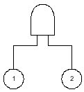
The data would be collected and used to calculate the PFDavg of each device
![]()
Boolean algebra, also known as cut-set math, is used to calculate the and gate. This yields:
![]()
Since these calculations are based on the PFDavg for a single device, it is easy to examine cases where the failure rates and testing frequencies of the two devices are not the same. The PFDavg for each event is simply calculated based on its failure rate and testing frequency. These PFDavg values are combined using the cut-set math.
Any of the terms discussed in the Simplified Equations overview can be included in the fault tree as events, such as systematic failure and common cause failure. The 1oo2 voting devices, including common cause, would appear as shown in Figure 2.
Figure 2. PFDavg for 1oo2 Voting Devices With Common Cause Consideration
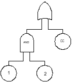
The independent failure rate contribution would be calculated as follows:
![]()
The common cause contribution to the PFDavg would be calculated as follows:
![]()
The common cause failure contribution can then be added to the independent failure rate contribution using cut-set math. For rare events, the PFDavg calculations would be as follows:

The systematic failure contribution to the PFDavg can be added in a similar fashion.
Determining The Spurious Trip Rate via Fault Tree Analysis
For the spurious trip rate calculation, the same graphical technique is used, as well as the same cut-set mathematics. However, the equations used to describe the individual events are based on frequencies not probabilities. For the 1oo2 voting devices, the fault tree is drawn as shown in Figure 3.
Figure 3: Fault tree for Spurious Trip for 1oo2 Voting Devices
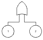
The spurious trip rate is calculated as follows:
![]()
Limitations of The Methodology
The derivation methodology for fault tree analysis is different from the Markov derivation methodology used in the other parts of TR84. While not truly a limitation of the methodology, the difference in the PFDavg values for some architectures has resulted in disagreement among TR84 members about the true definition of PFDavg . However, the difference in the overall results is seldom significant, but the reader is warned that there will be instances where simplified equations and fault tree analysis will not yield identical results.
There are three principle benefits associated with using Fault Tree Analysis for SIL verification. First, the graphical representation of the failure logic is easily understood by risk analysts, engineers, and project managers. Second, the method has been used by the process industry for risk assessment for many years, so there is already a resource base within many User companies, as well as outside consultants. Finally, the availability of software tools to facilitate the calculations improves the quality and precision of the calculation.
Conclusions
ISA-dTR84.0.02 is intended to provide guidance on how to calculate the SIL of a SIS. Since ISA-dTR84.0.02 is a guidance document, there are no mandatory requirements. The document was not developed to be a comprehensive treatise on any of the methodologies, but was intended to provide assistance on how to apply the techniques to the evaluation of SISs. Each Part expects the User to be familiar with the methodology and suggests that the User obtain additional information and resources beyond that contained in the technical report. The technical report was issued in draft in 1998 and should be released as final in 2000.
Simplified Equations and Fault Tree Analysis are two excellent techniques that can be used together to cost effectively evaluate SIS designs for SIL. Initial assessment of proposed options for input and output architectures can be performed quickly at various testing frequencies using Simplified Equations. When the overall SIS needs to be evaluated, Fault Tree Analysis is a proven technique that can model even the most complex logic relationships.
Acknowledgements
This paper was presented at Interkama, Dusseldorf, Germany, October 1999.
References
- "Application of Safety Instrumented Systems for the Process Industries," ANSI/ISA-S84.01-1996, ISA, Research Triangle Park, NC, 1996.
- "Process Safety Management of Highly Hazardous Chemicals; Explosives and Blasting Agents," 29 CFR Part 1910, OSHA, Washington, 1992.
- "Risk Management Programs for Chemical Accidental Release Prevention," 40 CFR Part 68, EPA, Washington, 1996.
- IEC 61508, 65A/255/CDV, "Functional safety of electrical/electronic/programmable electronic safety related systems," Parts 1, 3, 4, and 5, International Electrotechnical Commission, Final Standard, December 1998.
- IEC 61508, 65A/255/CDV, "Functional safety of electrical/electronic/programmable electronic safety related systems," Parts 2, 6, and 7, International Electrotechnical Commission, Final Draft International Standard, January 1999.
- Summers, A.E., "Techniques for assigning a target safety integrity level," ISA Transactions, 37, pp. 95-104, 1998.
- "Safety Instrumented Systems (SIS)—Safety Integrity Level (SIL) Evaluation Techniques, Part 1: Introduction," ISA dTR84.0.02, Draft, Version 4, March 1998.
- "Safety Instrumented Systems (SIS)—Safety Integrity Level (SIL) Evaluation Techniques, Part 2: Determining the SIL of a SIS via Simplified Equations," ISA dTR84.0.02, Draft, Version 4, March 1998.
- "Safety Instrumented Systems (SIS)—Safety Integrity Level (SIL) Evaluation Techniques, Part 3: Determining the SIL of a SIS via Fault Tree Analysis," ISA dTR84.0.02, Draft, Version 3, March 1998.
- "Safety Instrumented Systems (SIS)—Safety Integrity Level (SIL) Evaluation Techniques, Part 4: Determining the SIL of a SIS via Markov Analysis," ISA dTR84.0.02, Draft, Version 4, March 1998.
- "Safety Instrumented Systems (SIS)—Safety Integrity Level (SIL) Evaluation Techniques, Part 5: Determining the PFD of SIS Logic Solvers via Markov Analysis," ISA dTR84.0.02, Draft, Version 4, April 1998.
- "OREDA: Offshore Reliability Data Handbook," 3rd Edition, Det Norske Veritas Industri Norge as DNV Technica, Norway, 1997.
- "Guidelines for Process Equipment Reliability Data," Center for Chemical Process Safety of the American Institute of Chemical Engineers, NY, NY, 1989.
- "Non-Electronic Parts Reliability Data," Reliability Analysis Center, Rome, NY, 1995.
- Summers, Angela E., "Common Cause and Common Sense, Designing Failure Out of Your Safety Instrumented Systems (SIS)," ISA Transactions, 38, 291-299, 1999.
Techniques for Assigning A Target Safety Integrity Level
Angela E. Summers, Ph.D.
This paper was published in ISA Transactions 37 (1998) 95-104.
Abstract
The new ANSI/ISA S84.01-1996 (1) Application of safety instrumented systems for the process industries, standard requires that companies assign a target safety integrity level (SIL) for all safety instrumented systems (SIS) applications. The assignment of the target SIL is a decision requiring the extension of the process hazards analysis (PHA). The assignment is based on the amount of risk reduction that is necessary to mitigate the risk associated with the process to an acceptable level. All of the SIS design, operation, and maintenance choices must then be verified against the target SIL. This paper examines the six most common techniques currently utilized throughout the process industries: Consequence Only, Modified HAZOP, Risk Matrix, Risk Graph, Quantitative Assessment, Corporate Mandated SIL.
Introduction
The OSHA process safety management (PSM) and EPA risk management program (RMP) dictate that a process hazards analysis be used to determine the protective measures necessary to protect workers, the community and the environment. A compliant program will incorporate "good engineering practice," which means that the program follows the codes and standards published by such organizations as the American Society of Mechanical Engineers, American Petroleum Institute, American National Standards Institute, National Fire Protection Association, and American Society for Testing and Materials.
In February 1996, the Instrument Society of America published a standard ANSI/ISA S84.01-1996, "Application of safety instrumented system for the process industries" (1) . This standard became an American National Standards Institute (ANSI) standard in March 1997. With its acceptance as an ANSI standard, it will be enforceable under OSHA PSM and EPA RMP.
The new ANSI/ISA S84.01-1996 standard and the draft IEC 61508 (2) standard require that a target safety integrity level (SIL) be assigned for any new or retrofitted safety instrumented systems (SIS). The SIS consists of the instrumentation or controls that are installed for the purpose of mitigating the hazard or bringing the process to a safe state in the event of a process upset. A SIS is used for any process in which the process hazards analysis (PHA) has determined that the mechanical integrity of the process equipment, the process control, and other protective equipment are insufficient to mitigate the potential hazard.
The safety integrity level designations, provided in ANSI/ISA S84.01-1996 and IEC 61508 (draft), can be correlated to SIS availability requirements. As shown in Table 1, IEC 61508 (draft) recognizes SIL 4, which the U.S. domestic standard ANSI/ISA S84.01-1996 does not consider.
Table 1. Safety Integrity Level Correlation with Availability and Probability to Fail on Demand (PFD)
| Safety Integrity Level | Availability Required | Probability to Fail on Demand | 1/PFD | ||
| IEC 61508 |
4 | >99.99% | E-005 to E-004 | 100,000 to 10,000 | |
| ISA S84 |
3 | 99.90-99.99% | E-004 to E-003 | 10,000 to 1,000 | |
| 2 | 99.00 - 99.90% | E-003 to E-002 | 1,000 to 100 | ||
| 1 | 90.00 - 99.00% | E-002 to E-001 | 100 to 10 | ||
What does SIL mean? It should be understood that SIL and availability are simply statistical representations of the integrity of the SIS when a process demand occurs. The acceptance of a SIL 1 SIS means that the level of hazard or economic risk is sufficiently low and that a SIS with an availability of 90% (or 10% chance of failure) is acceptable. For example, consider the installation of a SIL 1 SIS for a high level trip in a liquid tank. The availability of 90% would mean that, out of every 10 times that the level reached the high level trip point, there would be one predicted failure of the SIS and subsequent overflow of the tank. Is this an acceptable risk?
A qualitative view of SIL has slowly developed over the last few years as the concept of SIL has been adopted at many chemical and petrochemical plants. As shown in Table, 2 this qualitative view can be expressed in terms of the consequence of the SIS failure, in terms of facility damage, personnel injury, and the public or community exposure.
Table 2: Qualitative view of SIL
| SIL | Generalized View |
| 4 | Catastrophic Community Impact |
| 3 | Employee and Community Impact |
| 2 | Major Property and Production Protection. Possible Injury to employee |
| 1 | Minor Property and Production Protection |
The above qualitative view leaves much open for discussion. What is minor? What is major? At what point, will a theoretical injury or fatality occur? There are no regulations that assign or assist in the assignment of a SIL to particular processes or chemical operations. Further, there are no regulations or standards to follow that recommend specific SILs for certain process hazards. The assignment of SIL is a corporate or company decision based on risk management and risk tolerance philosophy. The caveat is that ANSI/ISA S84.01-1996 does mandate that companies should design their safety instrumented systems (SIS) to be consistent with similar operating process units within their own companies and at other companies. Likewise, in the US, OSHA PSM and EPA RMP require that industry standards and good engineering practice be used in the design and operation of process facilities. This means that the assignment of safety integrity levels must be carefully performed and thoroughly documented.
Safety integrity levels are assigned after the process hazards analysis (PHA) has concluded that a safety instrumented system is required. A PHA is performed to identify potential hazards in the operation of a refining, chemical, or petrochemical process. PHAs range from the very simple screening analysis to the complex Hazard and Operability Study (HAZOP). The HAZOP (3) is a systematic, methodical examination of the process design that utilizes a multi-disciplinary team to identify hazards or operability problems that could result in an accident. The HAZOP provides a prioritized basis for the implementation of risk mitigation strategies, such as safety instrumented systems (SIS) or emergency shutdown systems (ESD).
When the HAZOP is completed, the risk associated with the process, in terms of severity and likelihood should be understood. The event severity is established based on some measure of the anticipated impact or consequence. This can include:
- On-site consequences
- worker injury or death
- equipment damage
- Off-site consequences
- community exposure, including injury and death
- property damage
- Environmental impact
- emission of hazardous chemicals
- contamination of air, soil, and water supplies
- damage to environmentally sensitive areas
The risk likelihood is determined by estimating the probability of expected occurrence. The likelihood is classified as high, medium or low rate of occurrence. This is often determined based on company operating experience or industry wide operation history.
The choice of the SIL assignment method is dependent on the existing corporate risk assessment methodology. There are several methods of converting HAZOP data into safety integrity levels (SIL), including:
- modified HAZOP,
- consequence only,
- risk matrix,
- risk graph,
- quantitative assessment, and
- Corporate mandated SIL.
It is necessary for the user to develop procedures and guidelines to ensure that any of the methods are used effectively and consistently. These methods will be discussed below, along with some criteria for choosing the method.
Modified HAZOP
The Modified HAZOP is an extension of the existing HAZOP process. It is a subjective assignment of the SIL based on the team’s qualitative understanding of the incident severity and likelihood. This method relies heavily on the experience and knowledge of the team members. The required experience and knowledge extends beyond simple understanding of the process operation. It must include an understanding of the process risk and the acceptable risk tolerance of the company. The SIL is assigned by qualitatively examining the risk potential and selecting a SIL that seems appropriate by the team’s estimation of the risk. Since the assignment is very subjective, there needs to be some consistency between the personnel on the SIL assignment teams from project to project.
Consequence Only
The most conservative technique, Consequence only, uses an estimation of the potential consequence of the incident. The incident frequency is not considered. Consequently, all incidents resulting in possible fatalities would have the same SIL no matter how remote or frequent the incident likelihood might occur. A Consequence only decision table may appear as shown in Table 3.
Table 3. Consequence only decision table
| SIL | Generalized View |
| 4 | Potential for fatalities in the community |
| 3 | Potential for multiple fatalities |
| 2 | Potential for major serious injuries or one fatality |
| 1 | Potential for minor injuries |
This method, while conservative, is the simplest tool to utilize, because the team does not need to estimate the likelihood of the incident, which is often the most difficult estimation for the team to make. This method is especially appropriate when the process history is very limited, which contributes substantially to the difficulty in defining the likelihood.
Risk matrix
One of the most common techniques, among refining, chemical and petrochemical companies, uses a risk matrix, which provides a correlation of risk severity and risk likelihood to SIL. Where the Consequence only technique results in a fixed response to a perceived hazard, the Risk matrix method allows the probability of the potential event to be considered during the assignment of SIL.
A corporate risk matrix provides control of the SIL assigned for a particular severity and likelihood. During the assessment of the incident severity and likelihood, the available layers of protection must be evaluated and their effect on the incident severity and likelihood must be determined. For risk reduction consideration, the layers of protections must be independent, verifiable, dependable, and designed for the mitigation of the specific risk. An example of the two dimensional Risk matrix is in Fig. 1.
Figure 1. Two dimensional risk matrix
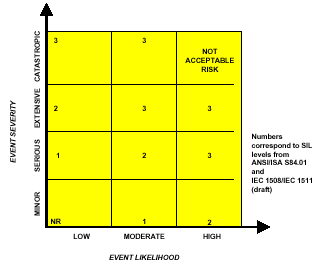
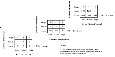
When it is desired that the method provide the capability to formally consider the independent protection layers, a three-dimensional Risk matrix may be used (fig. 2). The assessment of likelihood and severity is done without considering any additional protection layers. The amount of credit taken for the risk reduction inherent in each layer is controlled by the SIL values assigned in the three dimensional matrix. This provides better control in the amount of risk reduction that is assumed with each applied protection layer.
Figure 2. Three dimensional Risk matrix
For this method to be successfully used, the process and its associated risk must be well understood so that the qualitative estimation of the likelihood and severity can be made. The assessment of the likelihood is the most difficult for the assignment team to make, so there should be some general understanding among the assignment team as to frequency of past incidents in the facility or in the general industrial group.
Risk Graph
The international standard IEC 61508 (draft) provides an alternative method to the Risk matrix. It is called a Risk graph and provides a SIL correlation based on four factors:
- consequence (C),
- frequency and exposure time (F),
- possibility of avoiding the hazardous event (P), and
- probability of the unwanted occurrence (W).
This method is a qualitative technique that requires tools to be developed to ensure that the four parameters listed above are properly chosen. It focuses most of the evaluation on an individual person’s risk. The four factors are evaluated from the point of view of a theoretical person being in the incident impact zone. This method is consequence driven, but allows credit for controlling access to the facility. For this method, the likelihood and consequence are determined by considering the independent protection layers during the assessment.
Once these factors are determined, the risk graph is utilized to determine the minimum risk reduction level and associated SIL. As with the Risk matrix, a corporate risk graph should be developed. An example Risk graph is shown in Figure 3.
Figure 3. Example Risk graph
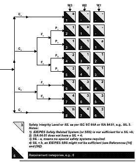
The Risk graph method uses the four parameters: Consequence-C, Frequency of exposure-F, Possibility of escape-P, and Likelihood of event-W. The analysis proceeds with a determination of each of the parameters, in terms of levels shown as subscripted numbers. The Risk graph shown in Fig. 3 has four levels for consequence, two levels for frequency, two levels for possibility of escape, and three levels for likelihood. As the subscripted numbers increase, the perceived hazard is higher. Each of these levels must be carefully defined on a corporate basis for the methodology to be useful. The consequence, C, is not simply defining the incident in terms of loss of containment, fires or chemical releases, as defined in the PHA process. It is examining the incident from the exposed person’s perspective in terms of an injury or fatality. For the example Risk graph shown in Fig. 3, the consequence levels are as follows:
C1 = Minor injury
C2 = Serious permanent injury to one or more persons
C3 = Death to several people
C4 = Very many people killed
In assessing the consequence, the following questions should be evaluated for the incident:
- Is there a potential for injury or fatality?
- Can the exposed person recover?
- Can the exposed person return to normal activities?
- Are the effects acute or chronic?
- Has consequence assessment been performed?
The answers to these questions enable a determination of which of the consequence levels should be chosen.
For the exposure frequency, F, the process unit must be evaluated in terms of the personnel presence and activity in the unit. For the example Risk graph, F1 is chosen for rare to more often exposure in the hazardous zone and F2 is chosen for frequent to permanent exposure in the hazardous zone. The questions for this parameter should address the following:
- Is the process unit remote or in the main personnel traffic area?
- How close are operation and maintenance stations?
- How often is operation’s staff in the vicinity?
- What about support staff, such as maintenance crews or engineering personnel?
- Is this a main travel area for access to other process units?
Possibility of escape, P, can be difficult for the hazards evaluation team to agree upon, because, as engineers and risk assessment people, there is a tendency to want to believe that people can always escape if there are alarms. However, time becomes an important factor in the escape. The example Risk graph uses P1 for possible under certain conditions and P2 for almost impossible. To determine whether it is truly possible or not, the question that should be asked is, "How easy is it to escape from the hazardous area?" Typical issues that should be addressed are as follows:
- Are the escape routes well marked?
- Can personnel in the exposure area readily recognize that a hazardous situation exists?
- Are there alarm sirens?
- Is there time to escape?
- What is the available escape time between alarm and incident?
- Have personnel been through accident scenario training?
- Do the personnel have historical experience with this scenario?
The probability of occurrence, W, is based on the likelihood of the event, which should be evaluated without taking into account any existing safety instrumented systems. The likelihood parameter in the Risk graph is the same as that determined for the Risk matrix. For the example Risk graph, the probability for occurrence is based on the following:
W1 = A slight probability
W2 = A medium probability
W3 = A high probability
The likelihood can be evaluated qualitatively or quantitatively. If a qualitative measure is used, the methodology must define the terms, low, medium, and high.
Quantitative Analysis
The quantitative approach to SIL assignment is the most rigorous technique to utilize. The SIL is assigned by determining the process demand or incident likelihood quantitatively. The potential causes of the incident are modeled using a quantitative risk assessment technique (5), such as that shown in Fig. 4, a fault tree. The quantitative technique is often used when there is very limited historical information about the process, so that the qualitative determination of likelihood is extremely difficult. The method does require a thorough understanding of the potential causes of the event and an estimated probability of each potential cause. Fig. 4 shows some of the potential failures that should be considered.
Figure 4. Quantitative Calculation of Process Demand

To determine the required SIL, the accepted or tolerable risk frequency is divided by the calculated process demand as follows:
![]()
The inverse of this equation has also been used to determine the risk reduction factor (RRF).
![]()
Whichever equation is used, the calculated risk reduction equates to the required safety integrity level.
Corporate mandated choice
The final technique is the least time consuming method, which is one being adopted by many small, specialty chemical plants that do not wish to devote extensive manpower to SIL assignment methodologies. This method recognizes that the greatest increase in cost occurs when the decision is made that the SIL must be higher than SIL 1 (6) . The selection of SIL 2 or SIL 3 forces the SIS design toward device redundancy and diversity. With this recognition, many small companies are taking the approach that "a safety system is a safety system and therefore should be SIL 3". This eliminates the arguments about whether escape is possible, someone will be injured or killed or the impact will be on-site and/or off-site. It saves time in the PHA process, reduces documentation in justifying the SIL choice, and ensures consistency across process units.
Demonstration of methodologies
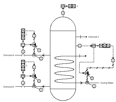
To demonstrate the methodologies described in this paper, a simple example will be provided. The reactor shown in Fig. 5 is utilized in the production of chemical C. Chemical A and chemical B are reacted to produce chemical C. Chemicals A, B, and C are flammable and, under certain conditions, explosive. The reaction is exothermic, so the reactor temperature must be controlled using cooling water. The flow rates of chemical A and chemical B are controlled, because the rate of reactant addition and the ratio of the reactant addition influence the reaction path. A process hazards analysis has documented that, if the flow rates of either chemical A or chemical B exceed certain levels, the reaction will runaway. In addition, the process hazards analysis has shown that if the reaction temperature is not controlled, the reaction path can shift, resulting in a runaway reaction. Both runaway reactions result in volatilization of the reactants and overpressure of the vessel.
Consequence analysis was performed for the various reaction scenarios. It was shown that ignition of the released contents of the vessel would create a pressure wave that would damage a large portion of the facility including the control room.
Figure 5. Simplified P&ID for exothermic reactor example
Modified HAZOP
The modified HAZOP would involve the discussion of the cause, consequence and safeguards for each potential incident. The keyword, More flow, would result in a discussion of the potential for runaway reaction, resulting in the potential overpressure of the vessel and loss of life. The required safeguard would be the installation of a SIS to shutdown the reactor on high reactant flow and on high pressure. The discussion of the likelihood and consequence would result in the team determining that SIL 3 is the best choice.
A similar discussion would occur when the keyword, High temperature, was used, resulting in a high temperature and high pressure initiated SIS. For this example, an action item is shown for the high temperature, "consider providing redundant reactor temperature transmitters." Since the control of the reaction temperature is key for the prevention of overpressure, the integrity of the process control layer should be improved by using redundant transmitters. Table 4 provides an example of the documentation that might be created for the Modified HAZOP.
Table 4. Example modified HAZOP
| Deviation | Cause | Consequence | Safeguards | Action | SIL |
| More Flow | FV-101 fails open | Potential for runaway reaction. Potential to overpressure the reactor with release of flammable/explosive contents. Poetnail for multiple on-site injuires or fatalities | High flow and High Pressure initiate SIS | 3 | |
| High Temperature | TV-103 fails closed or loss of cooling water supply | Same as above | Reactor High Temperature and High Pressure initiate SIS | Consider providing redundant reactor temperature transmitters. | 3 |
Consequence Only
The process hazards analysis identified that the consequence of any ignited release was damage to the control with mulitiple injuires and fatalities. Table 5 shows that this consequence would result in the selection of a SIL 3.
Table 5. Consequence Only Example Table
| SIL | Consequence |
| 3 | Potential for multiple fatalities |
| 2 | Potential for major serious injuries or one fatality |
| 1 | Potential for minor injuries |
Risk Matrix
The information developed during process hazards analysis would be used as the basis for determining the likelihood and severity of the potential incident. Since the high flow rate scenario is caused by a simple loss of process control, the likelihood of this event is high. The documentation has shown that the runaway reaction would result in an overpressure of the vessel, resulting in the potential for severe damage if the released contents are ignited. The severity would be rated as extensive. The two-dimensional matrix shown in Fig. 1 shows that a high likelihood and extensive severity event requires SIL 3. If the three dimensional matrix is used, the other layers of protection would need to be determined. For the runaway reactions involved in this process, the overpressure is developed too quickly to be relieved using a pressure relief valve. Therefore, the presence of the pressure relief valve cannot be used as a mitigating device in the SIL assignment. No acceptable layers of protection were identified during this analysis. Examination of Fig. 2 shows that, at IPL=low and at high severity/high likelihood, the assigned SIL would be SIL 3.
Risk graph
The process hazards analysis indicated the potential for multiple injuries and fatalities, so the consequence is C3. The frequency of exposure is high, F2, since the potential explosion will impact the control room. The Risk graph does not allow the use of possibility of escape at this consequence level (fatalities). The likelihood was determined to be high or W3. From the Risk graph shown in Fig. 3, the required SIL is SIL 4.
Quantitative assessment
A fault tree, such as the one shown in Fig. 5, could be drawn to model the process demand frequency or likelihood for the high temperature incident. This fault tree does not include all of the potential sequences associated with the production of high temperature. For the sake of simplicity, it has been limited to the temperature control loop, cooling water flow, and procedural errors. For completeness, the fault tree would need to be extended to include the effect of the reactant flow on the production of temperature, as well as other direct and indirect causes of high temperature.
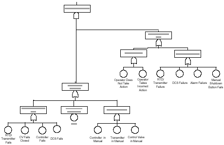
Data is collected from historical evidence and published data sources in order to quantify the fault tree. For this example, the fault tree yielded a process demand frequency of 0.01 per year. The corporate risk tolerance is 0.00001 per year. When the corporate risk tolerance is divided by the process demand frequency, the calculated risk reduction factor is 0.001 or SIL 3.
Conclusion
Unfortunately, there is no easy answer when it comes to assigning SILs. The choice involves examining safety, community, environmental, and economic risks. Most importantly, tools must be developed at the corporate level to ensure that the choice of SIL is consistent with a company’s risk management philosophy and that the assignment method is congruent with the existing characteristics of the corporate risk assessment methodologies. The methods presented are all equally useful in converting PHA data into safety integrity levels (SIL), including Modified HAZOP, Consequence only, Risk matrix, Risk graph, and Quantitative assessment, and Corporate mandated SIL. When choosing a method, there are a number of factors that should be considered:
- What type of method is currently used for corporate risk analysis?
- How complex is the process?
- Is the process well-understood?
- What is the operating experience and knowledge of process dynamics?
- Will the SIL assignment team be consistent from project to project?
Whichever method is chosen, it is necessary for the user to develop procedures and guidelines to ensure that the method is used effectively and consistently.
References
- ANSI/ISA-S84.01-1996 "Application of Safety Instrumented Systems for the Process Industries," Instrument Society of America S84.01 Standard, Research Triangle Park, NC 27709, February 1996.
- IEC 61508, "Functional safety of electrical/electronic/programmable electronic safety related systems," International Electrotechnical Commission, Draft, 1997.
- Guidelines for Hazard Evaluation Procedures, Center for Chemical Process Safety, American Institute of Chemical Engineers, New York, New York, 1992.
- Guidelines for Chemical Process Quantitative Risk Analysis, Center for Chemical Process Safety, American Institute of Chemical Engineers, New York, New York, 1989.
- Adamski, Robert S., "Design Critical Control or Emergency Shutdown Systems for Safety AND Reliability," Automatizacion 96, Panamerican Automation Conference, Caracas, Venezuela, May 1996.
- Windhorst, J.C.A., Strategic Initiative. Nova Chemical, Red Deer, AB, Canada.
Safety Requirements Specification in a Capital Project Environment
Dr. Angela E. Summers, P.E., President, SIS-TECH SOLUTIONS, LLC
PMB-295, 2323 Clear Lake City Blvd, Houston, TX 77062-8032
713-320-4777 (phone) 281-461-8109 (fax)
Presented at the Texas A&M Instrumentation Symposium 2000
Submitted for publication in Control Engineering
Abstract
The safety requirement specification (SRS) is a new documentation requirement of the safety system standards. It must be developed during the execution of a capital project involving Safety Instrumented Systems (SIS). In both the US domestic and international standard, the performance and functional requirements are defined in the SRS. These requirements provide the key measure by which the SIS design is compared and judged throughout the remainder of its lifecycle. Therefore, it is important to understand the contents, ownership, and appropriate timing of the SRS. Once understood, the project work breakdown can be modified to include this key deliverable in the execution of the SIS lifecycle. This paper will propose how to overlay the SRS deliverables with a typical project implementation cycle.
Introduction
The development of a safety requirements specification (SRS) is an important step in the safety instrumented system (SIS) lifecycle, presented in the US domestic and international SIS standards. All phases of design are judged against the SRS.
Unfortunately, neither standard provides a clear purpose, scope, or timing of the SRS. According to ANSI/ISA S84.01-1996 1 and draft IEC 61511 2 :
- The objective of the SRS is " to develop specifications for safety instrumented systems design."
- The SRS can be a collection of documents or information.
- The SIS lifecycle is shown as a series of steps leading many engineers to believe
that the SRS is generated as a single deliverable after the process hazards analysis (PHA). Compounding the situation, neither standard provides clear differentiation between the SRS and typical capital project documentation. This has resulted in a wide assortment of responses to the SRS. Some companies are essentially doing nothing, assuming that the SRS is covered by current documentation. Others have created a comprehensive, new document that the design team must complete. And, of course, there are many in the middle, filling in the gaps in their current documentation with any new requirements.
To determine how the SRS is best developed, it is necessary to back up and take the "big picture" approach. Elements of the SRS are developed, modified, or utilized throughout the lifecycle. This means that the SRS is not a document generated at a single point by the project team, but it is instead a document that evolves throughout the entire design. While the SRS serves as the basis for the SIS design, it is substantially more than a "specification" for the SIS design. It is used as the primary validation tool for the SIS design and is the basis for on-going management of change activities.
The United States Occupational Safety and Health Administration (OSHA) Process Safety Management (PSM) program requires the compilation and on-going maintenance "process safety information." The purpose of the process safety information is the documentation of identified process hazards and how these hazards are being managed during plant operation. The content of the SRS is essentially the process safety information for safety instrumented systems.
The SRS establishes the safety functional requirements for the SIS. These consist of the logic and actions to be performed by the SIS and the process conditions under which the actions are initiated. The functional requirements specification includes the following general topics:
- Safe state of the process
- Process inputs and trip points
- Process outputs and actions
- Functional relationships, failure modes
- Manual shutdown and reset requirements
- Maintenance/bypassing requirements
- Response time requirements
- Human machine interface requirements
The SRS also includes the safety integrity requirements that document the risk reduction allocated to each independent protection layer. The safety integrity requirements for the SIS provides the safety integrity level (SIL) and performance required for executing each safety function 3 . A critical input to the safety integrity requirements is the assumptions concerning any other independent protection layers used for risk reduction. The SIS performance criteria must include common mode failures, diagnostics, maintenance, functional testing, and reliability issues.
Taking its content into account, the following project lifecycle steps are affected by the SRS:
- Feasibility
- FEL (front end loading)
- Design
- Validation
- Operation
- Maintenance
- Training
- MOC (management of change)
The effect of the SRS on each of these steps varies. For a typical grass-roots project, the interaction is illustrated below with the initial step being "feasibility" and continuing clockwise around the figure. The important point of this illustration is that the SRS is central to the design of the SIS. All activities associated with the SIS either affect or are affected by the SRS. Therefore, the SRS must be developed and reviewed by a team of people with process, equipment, operating, and maintenance experience and knowledge.
SRS Lifecycle
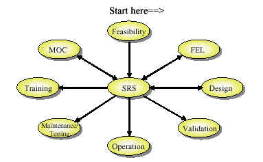
Starting with early feasibility studies, chemists and chemical engineers perform the research and development that is necessary to understand not only how to make product but also how to control the process. Potential incident scenarios are discussed, including the initiating cause of the scenario and the consequence. When building the pilot plant, these scenarios are used as the design basis for safeguards in the pilot plant. These safeguards often focus on the application of inherent safety principles to reduce the risk of the incident. If the residual risk is still too high, additional measures are taken, which typically include the application of independent protection layers. The lessons learned throughout the feasibility study process are critical inputs into the SRS.
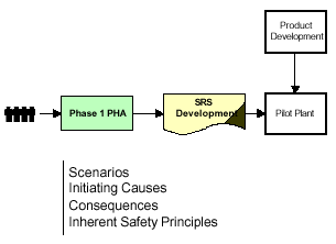
During front-end loading, the scenarios identified during the feasibility studies are examined, along with any other scenarios that the team may identify. After the examination of inherent safety principles, the unmitigated frequency of each potential incident is estimated. At this point, the risk associated with each incident is known and risk management decisions must be made. These decisions typically involve the use of passive protection systems (e.g. pressure relief valve), active protection systems (e.g. critical control systems and alarms or SIS), and consequence mitigation systems (e.g. fire and gas). Each of these protection layers is used to reduce the risk associated with each incident scenario to a tolerable level.
The SRS should include a description of how each of these protection layers are intended to function, including any assumptions made regarding their design integrity. Any special regulatory concerns, such as specific State or Government regulatory requirements or siting issues, should be documented. If nuisance tripping can cause cascade tripping of SISs in other units, this must be considered in the design basis.
Finally, the remaining SRS elements described in the standards in the safety integrity requirements and the safety functional requirements are developed as part of the basis of design specification or conceptual design. These elements include the following:
- Operating parameters
- IPL Setpoints
- IPL Functionality
- Engineering Calculations
- Special provisions or requirements
- Environmental
- Diagnostics
- Testing
- Materials of construction
- Security
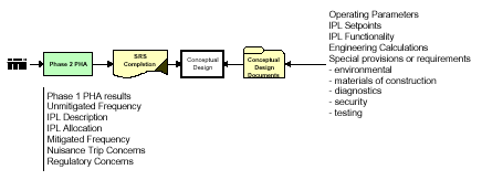
The detailed design is performed according to the conceptual design and the SRS. Any deviation from these documents should be evaluated to ensure that the risk reduction specified for each independent protection layer is not compromised. The detailed design documents include construction and installation drawings, engineering specification sheets, loop drawing, and procedures. When P&ID drawings are nearing completion, a HAZOP is typically performed to identify hazards or operability problems that could result in an incident. The draft SRS should be used to verify that all of these identified risks are mitigated to a satisfactory level. Thus, the HAZOP serves as a verification of the completeness of the design with respect to safety and the completeness of the SRS.
As described above, the development of the SRS for a grass roots facility occurs during feasibility and front-end loading. The completeness of the SRS is verified at the detailed design HAZOP. Any required modifications to the SRS should be documented through proper change management and revision control. The approved SRS becomes part of the process safety information, required in many countries as a demonstration of the risk analysis or functional safety assessment of the facility.
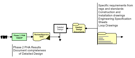
For an existing facility, the SRS is developed using existing process documentation. Often the connection between the HAZOP concerns and the installed instrumentation is not clear in any of the documents. The HAZOP can be used to identify the scenarios of interest, but a team of health and safety, process, operation, and maintenance personnel must be assembled to identify the existing safety functions that are used to mitigate the scenario risk. At some point, the required SIL should be determined. This target SIL should be compared to the actual, design SIL to determine whether design or testing frequency modifications are necessary.
Prior to start-up, the approved SRS is used to validate the installation, integrity, and functionality of the SIS. Any deviations from the SRS should be treated as safety-related and risk analysis should be performed to determine whether the deviation impacts the safety of the process. Validation documents that should be created prior to start-up are as follows:
- Instrument calibration sheets
- Loop checks
- Energy source verification
- Pre-startup safety review
- Pre-startup acceptance test
- Training on operational and maintenance procedures
The SRS provides input to the operation, maintenance, and testing of the SIS. During the SIS front-end loading, integrity requirements were established for the SIS. During normal operation, the actual design integrity is highly influenced by diagnostics, testing, bypassing provisions, SIS access security, and management of change (MOC). Consequently, administrative controls must be established to emphasize the importance of repairing diagnosed faults, testing/repairing instrumentation, and preventing bypass of SIS functions to ride out process upsets. The MOC program should be modified to ensure that any changes to the SIS are assessed to for impact on the required risk reduction documented in the SRS. Any modification must be documented in the SRS with revision control.
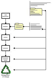
Why SRS?
The SRS is a thorough approach to the documentation of the SIS strategy for managing risk in the process. The SRS provides management with information concerning potential hazards and provides design documentation of the step taken to mitigate those hazards. The SRS provides assurance to insurers, regulators, plant personnel and corporate management that safety systems are in place, effective and being managed correctly. The SRS fits well into front-end loading and proper use of the SRS can reduce downstream project design changes. When the SRS information is shared throughout a Corporation for similar processes, best practices can be identified resulting in further cost savings and in the minimization of inconsistencies from one site to another. The SRS is a "living" document that provides the rationale behind the design of the SIS. By following the flowchart presented in this paper, the SRS can easily be integrated into the normal design process, resulting in the most cost effective implementation of the SIS standards.
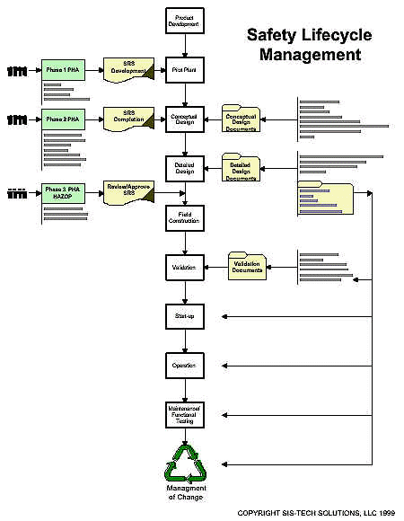
Sidebar - Roles and Responsibilities
Of all of the requirements in the standards, the SRS is the true ABM (anyone but me) deliverable. This is primarily due to its comprehensive coverage of safety, process, instrumentation, electrical, operation, maintenance, and testing issues. When this document is viewed as an evolving collection of information, it is easier to understand that the SRS is an Everyone deliverable. The roles and responsibilities matrix for the deliverables/documents can be summarized in the following table.
| Deliverable | Health, Safety, and Environment | Process Engineers and Chemists | I&E | Operations And Maintenance |
| Phase 1 PHA: SRS Development | L/A | P | ||
| Phase 2 PHA: SRS Completion | L/A | P | P | P |
| Phase 3 PHA: HAZOP | L/A | P | P | P |
| Conceptual Design (FEL) | R | L/A | P | R |
| SIS Detailed Design | R | R/A | L | R |
| Operating Procedures | L/A | P | P | |
| Maintenance and Testing Procedures | R | L/A | R | |
| Validation | R | P | L/A | P |
|
L: Lead P: Participate R: Review A: Approve |
||||

