
Evaluation of ControlValve Performance is Necessary in Plant Betterment Programs
Sanjay V. Sherikar, Ph.D., P.E.
CCI
22591 Avenida Empressa
Rancho Santa Margarita, CA 92688
Phone (949) 858 1877
Fax (949) 858 1878
E-mail:
Abstract
Control valves affect the performance of power plant in terms of output, heat rate, reliability and availability because they are the final control elements in the operation. Therefore, critical evaluation of control valves must to be an integral part of any plant betterment program because the ultimate goal of such efforts is to improve the efficiency and reduce costs. Even control valves in the few severe service applications, which affect efficiency more than the rest of the valve population, have traditionally not been included in such efforts.
Recent studies indicate that eliminating control valve problems alone can improve the heat rate of power plants in the range of 2% to 5%. The elements that are critical in realizing the potential benefits are: analyzing the whole system and quantifying the losses, identifying the root causes of the problems causing these losses and then, finally, eliminating the root causes of those problems. Methods to estimate loss due to control valve non-performance have to be judiciously applied, and sometimes developed, on a case-by-case basis, as shown by examples in this paper. The commonly observed causes of valve problems are discussed, followed by practical strategies for implementing solutions to the valve problems.
Besides the potential for heat rate and efficiency improvement, solving severe service valve problems also removes a major obstacle for the plants to operate for longer intervals between outages, reduce scope of outage maintenance and provides opportunity to upgrade systems to modern practices.
Introduction
Operating power plants reliably, at full power and maximum efficiency, is desirable because of the great economic significance. This affects the economics of the individual power station, the electric utility and the whole economy that depends on it. Therefore, a great effort is made at the design stage to ensure efficient and reliable operation of these plants on a daily basis.
Key parameters are monitored for overall plant efficiency as prescribed by the designers of each station. Traditionally, severe service control valves have not been included in the efficiency analysis. This may have been due to a combination of factors - their treatment only as “necessary evils” in control, poor recognition of their contribution to plant efficiency and, perhaps, a lack of systematic methods in quantifying their effect on efficiency. However, there is a growing awareness in this regard. This is reflected in the critical scrutiny given to severe service control valves, as opposed to general service valves, when building new power plants and in improving efficiencies of existing power plants.
Control valves are the final control elements in the operation of a power plant. Therefore, plant efficiency is directly affected by non-performance of the valves, either in terms of output or in terms of reliability and availability. Figure 1 shows a simple process in which a control system which generates the control signal, a valve which operates according to the signal and then a feedback sensor which relays the parameter being monitored to the control system. The weakest link in this control loop will be the limiting factor in the control of such a process. Even the sophisticated digital control systems (DCS) or modern feedback sensors cannot make up for the limitations in the performance of a control valve.
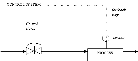
Figure 1. Simplified diagram of process control.
Severe Service Valves
Of the hundreds of control valves in any power plant, some valves experience tough operating conditions either at all times or under some operating conditions. These are known as severe service valves. Although they are few in numbers, they pose challenges to maintenance and operation. In most cases, problems are caused by the misapplication of general service valves in severe service duty. These severe service applications also affect efficiency more than the rest of the valve population. Conversely, for an existing power plant, eliminating problems in the severe service valves offers one of the quickest and effective means of improving its efficiency.
While contributions to plant efficiency loss from individual valve applications may be small, together they all can add up to be a significant value. When the invisible effects of the valve problems are taken into account, the net impact is even greater.
Severe Service Valve Problems and Their Impact on Plant Efficiency
The most critical factor used to judge the performance of a power plant is the heat rate of the unit. To achieve operation at lower heat rates the effect of controllable parameters on the plant heat rate should be quantified. Controllable losses typically are monitored and efforts are made to reduce these. By definition, and as a minimum, the fuel-cost penalty due to the controllable losses, which has direct impact on the efficiency of the unit, can be eliminated with proper solutions.
Examples of severe service control valve applications in the main power-generating loop in nuclear power plants are: main feedpump (MFP) minimum flow control, feedwater control, turbine bypass, atmospheric dump and emergency heater drains. In addition, there are many other severe applications in various other systems in nuclear plants, such as the residual heat removal (RHR), high pressure core injection (HPCI), service water, high pressure injection (HPI), reactor coolant system (RCS) and chemical volume control system (CVCS).
The typical problems caused by incorrect technology in severe service valves are:
- Premature trim and body erosion due to lack of control of fluid velocity along the flowpath
- Poor shutoff capability, i.e. leakage through the valve under closed condition, because of inadequate actuator thrust, damage to the sealing surfaces caused by high velocities and improper calibration
- Process controllability problems with the valve operating at lower openings
- Poor dynamic response
Most often, the visible effects of control valve problems are:
- Loss in production capacity
- Occasional plant trips
- Frequent maintenance
- Safety concerns
In addition, there are other costs, which may sometimes be invisible, because of the valve problems:
- Penalty in heat rate/ high operating cost
- Longer time for startup
- Lower Unit availability
-
Collateral damage to other expensive plant equipment (e.g., turbine, heater, boiler tubes) because of occasional transients that cause operation beyond normal operating conditions
-
Low flexibility in operation, e.g. part-load operation, or sliding pressure mode, in fossil power plants may not be possible even when it is desirable.
Expression of Loss Due to Control Valve Non-performance
There are several ways of expressing the estimates of loss due to control valve non-performance. The most direct, and perhaps the simplest, measures are those of generation capacity in MWe, heat rate and overall cycle efficiency.
In a majority of the cases, the plants can operate at the rated generation capacity because of built-in over-capacity in the auxilliaries, burning more fuel and the ability to replenish the losses in sub-systems. In such cases, the losses may be expressed in terms of Btu’s/hr directly, or in terms of “equivalent MWe”. In this context, equivalent MWe is defined as the additional electrical power output that the plant could generate by eliminating the existing control valve problems if there were no other limitations.
For quantifying inefficiencies due to control valves, the operational losses due to control valve problems can be categorized as follows:
-
Primary losses of energy
-
Secondary losses of energy
Examples of primary losses of energy are leakage or flow from turbine bypass valves, emergency heater drain valves, main steam drain valves and boiler feedpump recirculation valves. In general, it includes all “high-energy dump valves”, i.e. those with high energy at the inlet and dumping to atmosphere or the condenser or a drain tank, that should be shut tight during normal operation. The energy loss is easily quantifiable when the process parameters and leakage flow estimates are available. At best, more fuel has to be burnt to make up the loss of energy in the leakage flow; at worst, the plant’s load is limited and the maintenance cost is high.
In fossil-fired power plants, the primary losses also include the effect of leaking attemperator spray valves. In this case, the leakage flow causes the steam temperature to drop. As a result the boiler must be fired harder to raise the steam temperature to the set value. The penalty in heat rate as a result of this can be translated to efficiency loss. This loss is quantifiable from the data provided by the plant designer at the time of commissioning.
Secondary energy losses include those due to unavailability because of control valve problems, loss due to degraded operation because of poor controllability and second-order effects of control valve problems. These can be quantified using historic data of plant operation. Judgement based on prior experience, and understanding of plant operation, is required for estimation and to assess if they are significant.
Methods for Estimating Penalties Due to Control Valve Non-performance
Calculation of energy losses due to control valve leakage first require estimation of the leakage rate. Some of the methods that have been used for this purpose are based on:
-
Anticipated degradation of the specified shutoff leakage class
-
Typical damage observed in similar applications
-
Actual damage observed in the specific service
-
Process indications, pressure, temperature etc., in the system
-
Heat & mass balance analysis of well-defined control volume in the system.
The order above indicates increasing reliability of estimates going down the list.
Calculation Based on Anticipated degradation
As a general rule, “high-energy dump” valves are closed during normal operation and should seal very tightly when shut. In severe service applications, even a tiny leak path creates high velocity jets of leakage flow that damage sealing surfaces progressively, thereby creating a major leak. The ANSI class IV shutoff specification allows a maximum leakage equivalent to 0.01% of the capacity, Cv, of the valve. While this may seem pretty tight, this performance for a severe service application may be achieved in factory test and not much beyond that. In practice, the degradation of shutoff of such severe service valves has been observed to cause leakage flow equivalent of 1 to 5% of the valve capacity, Cv.
Calculation Based on Typical Damage
Examples of typical trim damage in severe service control valves are shown below in Figures 2a-c. Such damage to the sealing surfaces of a control valve can be translated into area of the leak path for which the leakage flow capacity, Cv, can be readily calculated. In such instances, the actual leakage flow when the valve is closed can be calculated from the known process parameters upstream and downstream of the valve, and from the leakage flow Cv.
If the typical damage is known from previous maintenance history, it can be used directly. A calculation based on this method is shown here for the case of a main feedpump (MFP) recirculation valve in a pressurized water reactor plant.
|
Case - MFP recirculation valve : The cage from this valve after one cycle of operation is shown in Figure 3. Measurements of the damage to the sealing surface indicate that its total cross-sectional area to be 0.087 sq. in. |
Is this estimate credible? - It has been reported [Reference 4] that PSE&G, Salem, gained 2 MWe per Unit by eliminating the leakage in their MFP recirculation valves!
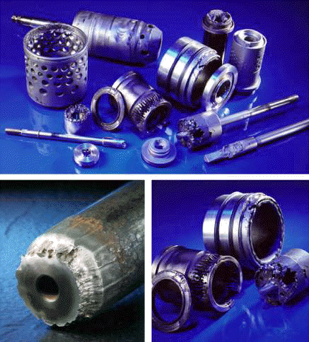
Figure 2 (a) to (c), clockwise from top
When such information on damage to the sealing surfaces is lacking, prior experience of typical damage in the specific application can be used.
As a quality check, the leakage Cv should be compared to the full Cv of the valve.
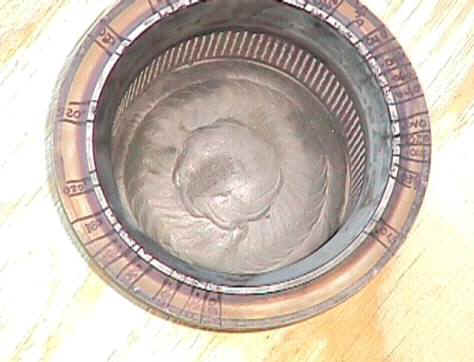
Figure 3. Damaged trim from main feedpump (MFP) recirculation valve showing areas of damage on the sealing surface. The depth and width of individual damage locations were measured to arrive at an equivalent leakage area.
Calculation Based on Available Process Indications
In some instances, pressure and temperature indications may be available across an element, which is located downstream of the leaking control valve, and which offers resistance to flow. In such cases, the geometry of this component, or its design data, may be used to calculate its equivalent flow capacity, Cv. From this and the process indications available, leakage flow can be estimated. At times, a flow transmitter is located in the same line as the control valve. Then such valves leak, the leakage can be read directly from this indication.
Estimate Based on Heat and Mass Balance
This requires a true system analysis and use of data that is available at the plant. In this type of procedure, a control volume is defined in the vicinity of the subject valve(s) and conservation principles are applied using the actual process conditions at a given time.
Figure 4 shows the final result for such an analysis for a start-up system in a fossil power plant. To arrive at this heat balance, mass balance and power balance equations were applied to the control volume shown, and also to heaters 1 &2 and the HP-IP turbine.
Estimation of Secondary Losses
Secondary losses, which include those due to unavailability and degraded operation resulting from poor control valve performance, can be estimated from power plant’s operational history and records. They are silent MW-killers as well and have to be estimated on a case-by-case basis.
Non-operational Costs
Besides the operational inefficiencies as described above, there are additional costs resulting from control valve problems. These include the cost of maintenance, spare parts, inventory, and most importantly the additional time required to attend to the problematic valves during planned shutdowns. The collateral damage cause by valve problems must also be taken into account in the cost-benefit analysis of the solution.
Recovering Losses due to Valve Problems
When a control valve continues to be problematic despite good maintenance practices and skilled staff, it is the first clue that incorrect technology is being applied in that service, which is not suitable for the specific application requirements.
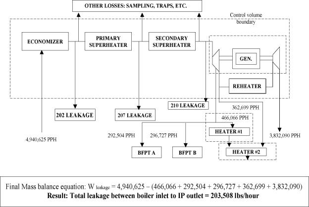
Figure 4: Final mass balance between boiler inlet and IP turbine outlet to determine total leakage from the control volume.
Identifying the root cause is the first step in solving problems in an existing valve and recover the losses that they cause. Then follows the step of ensuring that the correct valve technology is used in the case of new applications.
All severe service applications are not the same. This makes the details of each application all the more important. A discussion of the causes of valve problems in severe service applications, and the importance of addressing their root cause, can be found in References 1-3.
System Improvements
The power plant designers use the best technology for various systems and sub-systems that is available at the design stage - sometimes! Where that is not the case, and just with the advancement in technology over the years, plant betterment programs are an excellent opportunity to simplify systems and modify operations where it is beneficial.
Figures 5 (a) and (b) show simplification of controls in the feedwater system in a combined cycle plant. With the correct technology for control valves, this solution reduces valve maintenance drastically while solving root cause of problems specific to those valves.
Some examples of system improvements that have been realized by different power plants are:
- Flexibility in operation,
- Elimination of valves and some of the system components altogether,
- Combining the function of two or more valves into one,
- Incorporating warming flow function in upstream valves instead of separate warming lines,
- Elimination of safety-related problems.
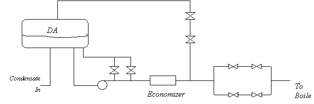
Figure 5a: Schematic of the flow diagram showing the locations of severe service valves
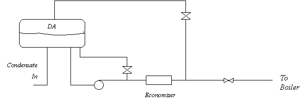
Figure 5b: Simplified feedwater system and the locations of severe service valves.
Conclusions
In conclusion,
-
Control valve performance must be evaluated as part of any plant betterment program. Such an effort, especially focussed on severe service valves, can improve plant in plant efficiency and reliability.
-
Evaluation of system as a whole is a key ingredient in eliminating losses due to severe service control valve problems.
-
Evaluation of control valves in plant betterment programs provides opportunity to upgrade systems to modern practices.
-
Quantification of losses due to control valve problems is possible by evaluating the system operation and the data that is generally available.
-
Elimination of severe service valve problems removes a major obstacle for the plants to operate for longer intervals between outages, and/or reduce outage maintenance.
References
- Sherikar, S.V. Technology In Severe Service Control Valves, 15-th Annual Air-Operated Valve Users Group (AUG) Meeting, Tuscon, AZ, June 9-12, 1998.
- Miller, H.L., and Stratton, L., Fluid Kinetic Energy As A Selection Criteria For Control Valves, ASME Paper FEDSM97-3464.
- Miller, H.L., Frequent Control Valve Problems, Seventh EPRI Valve technology Symposium, Incline Village, NV, May 26-28, 1999. [to be presented]
- Coleman, M., 15-th Annual Air-Operated Valve Users Group (AUG) Meeting, Tuscon, AZ, June 9-12, 1998. [private communication]