
High Integrity Pressure Protection Systems (HIPPS)
These are sometimes identified as
High Integrity Pipeline Protection Systems
Go to Specific Subject: High Integrity Pipeline Protection Systems - Description | Integral Mechanical HIPPs systems - Using Mechanical Initiators | Full Electronic HIPPS - with Electronic Pressure Transmitters | HIPPS Technical Papers and Applications | HIPPS Application Examples | HIPPS Systems Basics | HIPPS Design | Subsea HIPPS | Flare Load Mitigation Using HIPS | HIPPS Standards and Recommended Practices |
High Integrity Pipeline Protection Systems Description
These systems have been utilised in Germany for over 30 years and are proven to be extremely reliable in very rapid isolation of pipelines.
They are so reliable that the need for other safety related devices such as Safety Relief Valves can be minimised. They have the following advantages:
- Negating the need for flare systems to be sized for the case of a well failing to close.
- Production piping downrating, giving potential cost benefits of more than 25%
- Fast inventory isolation within two seconds
- Huge capital cost savings
HIPPS Systems reduce the need for traditional mechanical relief devices and the level of flaring in oil and gas applications. New installations can use the benefits to minimise the requirement for pressure relief valve manifolds and flare systems. On existing processing plants HIPPS Systems may eliminate the need to upsize the flare and the relief valve manifold as a result of increased throughput and in some cases actually provide the technology to remove an existing system. Installing a HIPPS system at the wellhead or pressure source allows the downstream piping to be down rated and as a result reduce capital expenditure. On offshore installations flaring can be significantly reduced and on new installations, significant weight savings may be attained with the use of HIPPS.
The HIPPS design must be in accordance with IEC 61508 /61511. These standards define the configuration of the Certified (Typically TUV) Safety Instrumented System (SIS) to provide the necessary risk reduction and meet the required Safety Integrity Level (SIL). The principal of operation is that the 2003 voted redundant pressure instrumentation trips on high pressure and isolates the pipeline very rapidly (typically within two seconds) by rapidly closing the valve. Dependant on the level of reliability required sometimes two HIPPS systems are installed in series. The need for this is determined by reliability analysis against a required facility reliability figure. These figures are determined by factors such as safety, environmental, public perception of a prescribed event and cost of an event.
Typical Applications:
- Onshore Gas Pipelines
- Offshore and Onshore Gas Well Pipelines
- Offshore Subsea Applications
Integral Mechanical HIPPs systems using Mechanical Initiators
In 1974 the German DVGW certified the Mokveld final element including mechanical initiators in accordance with EN 14382 (former DIN 3381). Since that date Mokveld has field experience with safety shut-off valves (with actuator and initiator) closing within 2 seconds. The main features of Mokveld’s integral mechanical HIPPS are;
- Integrated safety loop to IEC 61508 / EN 12186
- Safe and simple
- Option not requiring external energy (stand-alone HIPPS)
- No wiring required
- Set point accuracy < 1%
- System to SIL 3 or 4
- Third party validated failure data
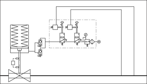

Integral Mechanical HIPPs system
Full Electronic HIPPS - with Electronic Pressure Transmitters
Full Electronic HIPPS - with Electronic Pressure Transmitters - When designing a HIPPS it is best to treat a HIPPS (and other SIS) as a complete certified functional loop and not on separate component level. Safety wise the HIPPS loop is designed in accordance with IEC 61508 and 61511. On the specification side of the final element the design is in accordance with EN 14382 (DIN 3381). The misunderstanding that ‘system’ stands for controller and that a SIS can be designed on component level, is the cause of the biggest problem in the implementation of HIPPS. The under specification of mechanical components and the acceptance of component Safety Integrity Level (SIL) certification, instead of verification of the complete loop SIL is still a pitfall. The main features of a full electronic HIPPS are;
- Integrated safety loop to IEC 61508 / EN 12186
- No limit on distance between transmitters and final element
- ommunication with Plant Safety System
- Possibility of integrated monitoring
- Hard-wired solid-state logic solver
- System to SIL 3 or 4
- High integrity manifold block for safer operation
Full Electronic HIPPS - with Electronic Pressure Transmitters
HIPPS Technical Papers and Applications
The following technical papers, articles and application examples are from Mokveld.
What is HIPPS? - HIPPS is an abbreviation of “High Integrity Pressure Protection System”. HIPPS systems are applied to prevent over-pressurisation of a plant by shutting-off the source of the high pressure. In traditional systems over-pressure is dealt with through relief systems. Relief systems have obvious disadvantages such as release of (flammable and toxic) process fluids in the environment and often a large footprint of the installation. With the increasing environmental awareness relief systems are no longer an acceptable solution. HIPPS provides a technically sound and economically attractive solution to protect equipment in cases where High-pressures and / or flow rates are processed, the environment is to be protected, the economic viability of a development needs improvement and the risk profile of the plant must be reduced. HIPPS is an instrumented safety system that is designed and built in accordance with the IEC 61508 and IEC 61511 standards. This useful paper describes the technology well.
Shutoff Valves - This paper highlights the HIPPS applications.
Considerations in Designing HIPPS - Willem-Jan Nuis / Rens Wolters - HIPPS is an abbreviation for High Integrity (Pressure) Protection System, which is a specific application of a Safety Instrumented System (SIS) designed in accordance with IEC 61508. The function of a HIPPS is to protect the downstream equipment against overpressure by closing the source. Usually this is done by timely closing one or more dedicated safety shut off valves to prevent further pressurisation of the piping downstream of those valves.
Axial Excellence in China's Gas Transmission Network - Chris Charles and Machiel Bosma - Since the early 1900's an exceptional valve concept was used in hydro-power plants: the axial flow valve. Axial flow refers to the streamlined symmetrical and unrestricted flow path between the valve inner and outer body. In the 1950's Mokveld acknowledged the advantages and adopted the concept into their control valves designs. Over the last decades, this axial control valve has captured a strong position across the full range of gas and oil segments; production, processing, transmission, storage and distribution. In this article, Mokveld presents some benefits of the use of axial control valves and provides some specific project application examples of their engineered valve solutions in China.
Partial Stroking on Fast Acting Applications - Willem-Jan Nuis / Rens Wolters - A proof test is a periodic test of the safety instrumented system, IEC 61508 adds that the target should be to detect 100% of all dangerous failures and all safety functions should be checked. Based on this we feel that partial stroking should not be considered a proof test. Partial stroking is born out of and focused on the breakaway torque of a ball valve. Partial stroking does not verify if the final element performs its safety function that is of course closing within a certain time. Therefore partial stroking should be considered on its best a diagnostic test. In some respect this could be contradicted while most partial stroke devices do not perform the test automated and do not shut-down the safety system when a fault is detected. We will however consider it a diagnostic test.
Increased Demands for HIPPS Final Elements - Rens Wolters describes the impact of the new IEC 61508 Edition 2010 on final elements and HIPPS - In the oil and gas industry protection against high pressure is increasingly performed by means of instrumented systems rather than mechanical safety relief valves. When the risk is high and the response time is short this application is often referred to as HIPPS (High Integrity Pressure Protection System). The applicable standards - IEC 61508 and IEC 61511 - use the generic term SIF or SIS (Safety Instrumented Function or System), whereas the industry uses HIPPS for this specific application. In the standards the element that shuts-off the incoming flow and isolates the high pressure source (on-off valve) is called the final element. A new revision of the IEC 61508 was published in 2010 and seriously impacts the HIPPS final element.
Valves/Actuator Combinations - Rens Wolters - In 2010 a new revision of the IEC 61508 was formally published. The previous version dated back to 1998 and since then it is used in the Oil and Gas industry for over-pressure protection systems. This paper focuses on the modifications in the IEC 61508 related to the final elements and as example an application in the Oil and Gas industry is used - from Mokveld and TUV.
Subsea HIPPS - HIPPS is an instrumented safety system that is designed and built in accordance with the IEC 61508 and IEC 61511 standards. Additionally API RP 17O - Recommended Practice for Subsea HIPPS - provides guidelines for using the IEC standards in subsea systems. These international standards refer to safety functions (SF) and Safety Instrumented systems (SIS) when discussing a solution to protect equipment, personnel and environment. A system that closes the source of over-pressure within 2 seconds with a determined reliability level is usually identified as a HIPPS. A subsea HIPPS is a complete functional loop consisting of; (a) The initiators that detect the high pressure (b) A logic solver, which processes the input from the initiators to an output to the final element and (c) The final elements, that actually perform the corrective action in the field by bringing the process to a safe state. The final element consists of a valve and fail safe actuator and possibly solenoids.
The Application of Safety Integrity Level (SIL) - Position Paper of the SIL Platform - This Superb document put together by Mokveld by an Expert Panel of authors for Safety Instrumented Systems Engineers Covers Questions as follows:
- What is the SIL platform?
- Why Issue a SIL Statement?
- What are the Basics of SIL Implementation?
- How do I Establish a SIL implementation?
- Which SIL subjects are covered in this Paper?
- What is a Systematic Design Approach?
- Why is a Systematic design Approach Important?
- What are the Pitfalls in Establishing a Systematic Design Approach?
- How do I Establish a Systematic Design Approach?
- What is Instrument Failure Data
- Why is Instrument Failure Data Important?
- What are the Pitfalls in Using Instrument Failure Data?
- How do I Correctly Apply Instrument Failure Data?
- How do I Use of Diagnostic Coverage Factor (DFC) and Safe Failure Fraction (SFF)?
- What are Hardware Safety Integrity Architectural Constraints?
- What are Proof Tests of Safety Instrumented Systems?
- What is Safety Lifecycle Management?
HIPPS Application Examples
Integral Mechanical HIPPS in Argentina - Stand-alone HIPPS in remote area
Other Useful Links to HIPPS Technical Papers and Articles
HIPPS Systems Basics
High Integrity Pressure Protection System - A High Integrity Pressure Protection System (HIPPS) is a type of safety instrumented system (SIS) designed to prevent over-pressurisation of a plant, such as a chemical plant or oil refinery. The HIPPS will shut-off the source of the high pressure before the design pressure of the system is exceeded, thus preventing loss of containment through rupture (explosion) of a line or vessel. Therefore, the HIPPS is considered as a barrier between a high-pressure and a low-pressure section of an installation. Covers Traditional systems, Advantages of HIPPS, Components of HIPPS, HIPPS Diagram, Standards and Design Practices -from Wikipedia, the free encyclopedia.
HIPPS-High Integrity Pressure Protection Systems - By now if you have been working in the process industries (like chemicals, oil & gas, petrochemicals and so on) for some time, you must have come across the term HIPPS. What is it? It is an acronym for High Integrity Pressure Protection Systems. These protection systems can be considered to a special subset of Safety Instrumented Systems, that are meant to provide protection to pressurized equipment (tanks, pipelines and so on) against overpressure and consequent rupture. Thanks to Abhisam Software.
HIPPS Solutions - Safe Operation and Nonstop Availability - The main reasons for using HIPPS (high-integrity pressure protection systems) are safety, environmental and economic. Safety to ensure that you can confidently operate close to design limits. Environmental to avoid unnecessary flaring and thereby limiting air emissions. And economic to reduce costs, because it is always cheaper to use HIPPS than to install full-flaring capacity and full-schedule piping and equipment. The continuous operation of equipment is a prerequisite. Nonstop operation - this is the advantage offered by HIMA HIPPS solutions. All applicable standards up to SIL 3 and even SIL 4 are also met.
High Integrity Pressure Protection System (HIPPS) - Andrew Chu - A High Integrity Pressure Protection System (HIPPS) is a Safety Instrumented System (SIS) designed to prevent an unsafe condition caused by pressure arising (e.g. due to separator outlet blocked in the choke valve downstream, blocked pipeline, etc). The decision to utilize a HIPPS in addition of utilize a PSV shall be based on the study of risk. The aim of this study is to determine a certain SIL requirement. This study will conclude whether some process condition need to have a HIPPS or its ok to protect it by a PSV valve only - from the Instrument Engineers Blogspot.
HIPPS Design
High Integrity Pressure Protection Systems (HIPPS) - Angela E. Summers, Ph.D., P.E., President, SIS-TECH Solutions, LLC - Fortunately, API 521 and Code Case 2211 of ASME Section VIII, Division 1 and 2, provide an alternative to pressure relief devices - the use of an instrumented system to protect against overpressure. When used, this instrumented system must meet or exceed the protection provided by the pressure relief device. These instrumented systems are safety instrumented systems (SIS), since their failure can result in the release of hazardous chemicals and/or the creation of unsafe working conditions. As SISs, they must be designed according to the United States standard ANSI/ISA S84.01-1996 or the international standard IEC 61511. The risk typically involved with overpressure protection results in the need for high SIS integrity; therefore, these systems are often called High Integrity Pressure Protection Systems (HIPPS) or High Integrity Protection Shutdowns (HIPS) - from SIS-TECH Solutions and people.clarkson.edu.
High Integrity Protection Systems For New And Existing Vessels - Bryan A. Zachary and Angela E. Summers, Ph.D., P.E. - High Integrity Protection Systems (HIPS) are Safety Instrumented Systems (SIS) implemented to address overpressure scenarios in lieu of a pressure relief valve (PRV). HIPS essentially replaces the PRV for those scenarios that the SIS is designed to prevent. HIPS applications are generally pipeline and pressure vessel overpressure protection. Thanks to SIS-TECH Solutions.
High Integrity Protective Systems for Reactive Processes - Angela E. Summers, Ph.D., P.E - LP Industry standards from the American Petroleum Institute (API) and American Society of Mechanical Engineers (ASME) provide criteria for the design and protection of vessels from rupture or damage caused by excess pressure. In conventional design, pressure relief devices, such as pressure relief or safety valves, are used as the primary means of pressure protection. However, in many reactive applications, the use of a pressure relief valve (PRV) is impractical. Alternative methods of preventing overpressure must be utilized to achieve measurable risk reduction. Fortunately, API 521 and Code Case 2211 of ASME Section VIII, Division 1 and 2, provide an alternative to PRVs - the use of a safety instrumented system. Since these safety instrumented systems must achieve a high safety availability, they are often referred to as high integrity protection systems (HIPS). This paper will discuss how to assess, design, and implement HIPS to effectively manage potential overpressure of equipment used for reactive processes - Thanks to SIS-TECH Solutions.
Justifying the use of High Integrity Pressure Protection Systems (HIPPS) - Edward M. Marszal, P.E., C.F.S.E. and Kevin J. Mitchell, P.E., C.F.S.E. - As chemical plants and petroleum refineries plan for future expansion, the capability of existing pressure relief systems to safely dispose of higher capacities is often a significant constraint. Current codes and standards now allow for the use of High Integrity Pressure Protection Systems (HIPPS) in lieu of increasing the capacity of emergency relief systems. There is a significant body of knowledge on how to design a HIPPS system once the requirement for one has been established. However, there is gap in knowledge of what situations allow for HIPPS and what practical steps can be taken to determine when a HIPPS is justified. This paper describes the analytical techniques that can be used by engineers to justify a design using instrumented protection in lieu of upgrading the relief system. A review of applicable requirements from codes and standards is included along with risk-based methods to ensure a HIPPS design is as safe as - or safer than - conventional relief design - from Kenexis.
Process Guidelines for Designing HIPS - This guide is intended to provide guidelines for Process engineers in charge of defining High Integrity Protection Systems (HIPS) during conceptual phases / preproject and/or supervising the process aspects of HIPS design performed by Contractors during project phases. You will have to log in to scribd to download this document.
HIPPS - for Cost-Effective Risk Reduction - Ken Bingham and Scott Lawson - With the oil and gas sector booming, many hydrocarbon processing facilities are trying to increase production to meet rising demand. These plants, initially designed and engineered, sometimes decades ago, to deliver a specific level of production, are being expanded or revamped in some way. When new gas production sources are tied into a gas plant, for example, the existing pipelines and processing equipment face the risk of overpressure in excess of design capacity. This may result in the unplanned release of hydrocarbons into the atmosphere via a triggering of a mechanical relief device such as a PSV (pressure safety valve), the undesirable burning of these hydrocarbons through the flare system or the worst case scenario of a rupture, fire and explosion. With the adoption of various standards including ASME, API, and the performance based, non-prescriptive standards IEC 61508 and IEC 61511, conventional thinking is evolving to include the application of high reliability safety instrumented systems (SIS) to replace and lessen the need for additional PSVs and expanded flare systems. HIPPS, an abbreviation for high integrity pressure protection system, is a specific application of a SIS designed in accordance with IEC 61508 which is growing in popularity. With HIPPS, the protection against overpressure is achieved by quickly isolating the source causing the overpressure, as compared to conventional relief systems where the overpressure is relieved to atmosphere - from ACM.
HIPPS-Based No-Burst Design of Flowlines and Risers - Nikolaos Politis, Hugh Banon, and Christopher Curran - A methodology is proposed for design of subsea flowlines and risers coupled with a subsea high-integrity pressure protection system (HIPPS) for fields with high shut-in tubing pressure (SITP). The proposed approach uses a design pressure that is lower than the SITP while maintaining a high reliability against burst failure. This approach enables an inherently safer design and ensures that the system integrity is not compromised in the unlikely event that HIPPS valves fail to close upon demand. The proposed design methodology is supported by a combination of analytical and experimental results. Further, an example is provided for demonstration purposes - from spe.org
Safety Instrumented Systems for the Overpressure Protection of Pipeline Risers - This provides guidance on pipeline riser system pressure containment, and on the overpressure protection of riser systems by means of instrumented systems which are remotely located on a normally unattended installation (NUI) or subsea- from the HSE UK.
High Integrity Protection Systems (HIPPS) - Making SIL Calculations Effective - Jean-Pierre Signoret - In the oil industry, traditional protection systems as defined in American Petroleum Institute (API) 14C are more and more often replaced by high integrity protection systems (HIPS). In particular, this encompasses the well-known high integrity pressure protectionsystems (HIPPS) used to protect specifically against overpressure. As safety instrumented systems (SIS) they have to be analysed through the formal processes described in the International Electrotechnical Commission (IEC) 61508 and IEC 61511 Standards in order to assess which Safety Integrity Levels (SIL) they are able to claim. Originally printed in Exploration & Production: The Oil and Gas Review 2007 - OTC Edition - Thanks to Touchoilandgas.com
Wellhead Flowline Pressure Protection Using High Integrity Protective Systems - Angela E. Summers, Ph.D., P.E., President, SIS-Tech Solutions, LP Bryan A. Zachary, Director, Product & Application Engineering, SIS-TECH Solutions, LP - For many years, owner/operator pipe specification practices have required that wellhead downstream piping be adequate to sustain a full wellhead shut-in. This inherently safer design practice ensured that flowline pipe was specified with a maximum allowable working pressure (MAWP) equal to or greater than the maximum pressure expected to be produced by the well. This practice has been proven to provide adequate protection in thousands of wellhead installations throughout the world. Inherently safer practice has been challenged recently with the introduction of electric submersible pumps (ESPs) in new and existing wells. The maximum discharge pressure under block-in conditions is greater than the MAWP of existing flowline pipe. A safe alternative to replacing the pipe is the use of a high integrity protective system (HIPS) designed and managed as a safety instrumented system (SIS). While the HIPS protects the flowline, the implementation of the HIPS introduces a new cause for blocked ESP discharge, which can result in significant ESP damage and production losses. This new hazard scenario must be addressed in the overall risk reduction strategy for the ESP and pipeline. This presentation explains how HIPS can be applied as a layer of protection against flowline overpressure in single and multiple wellhead installations. It also discusses how HIPS implementation affects the necessary ESP protection.
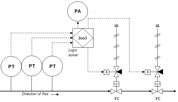
Advanced Solutions Key to Reliable HIPPS - Carsten Thoegersen - HIPPS are part of the safety instrumented system (SIS) and designed to prevent overpressure by shutting off the source and capturing the pressure in the upstream side of the system, thus providing a barrier between the high pressure and low pressure sides of an offshore topsides production facility. The tight shutoff will prevent loss of the containment and eliminate fugitive emissions. In this regard, HIPPS are seen as the "last line of defence." A typical HIPPS will include two or three final elements in series, often required to shut down within 2-3 seconds for gas and 6-8 seconds for liquids, depending on the pipeline pressure, flow rate, and the diameter and class of the pipeline. The initiator of the shutdown sequence (peak pressure surge) will be detected by a pressure sensing system. In the associated diagram, three sensors are connected to the logic solver, which is configured to vote with a 2oo3 logic system (2 out of 3). If the predefined parameters for pressure are exceeded, the logic solver will shut down the final elements and the process. The 2oo3 configuration is usually preferred for HIPPS, since it provides availability as well as reliability for the system - from Offshore Mag and Emerson Process Management.
Logic Solver for Overpressure Protection - The aim of this paper is to explore some of the possibilities available to the SIS designer of an High Integrity Pressure Protection System for the logic solver and to show examples of straightforward system topologies and their associated safety integrity level (SIL) calculations. A general step-by-step procedure to define and evaluate an SIS is suggested in the Appendix. The examples used in this paper illustrate how the procedure is applied in specific cases - from Moore Industries.
Subsea HIPPS
High Integrity Pressure Protection Lowers Subsea Costs - Ian Ramsay-Connell - Several North Sea examples illustrate the advantages of install ing high-integrity pressure protection systems (HIPPS) on subsea wells. Many published papers discuss the benefi ts of subsea HIPPS and many studies show the potential cost-benefi t analysis of this technology in deepwa ter applications - from Yokogawa.
HIPPS Protects Subsea Production in HP/HT Conditions - Lars Bak - Lilleaker Consulting AS - Roald Sirevaag and Halvor Stokke -The subsea production system for the high pressure/high temperature (HP/HT) Kristin field was developed to accommodate its shut-in wellhead pressure of 740 bar (74 MPa) and flowing temperature of 157° C (315° F). This required protecting the flowlines and risers from overpressure. The Kristin field began production in Nov. 2005, and in Aug. 2006, five of six subsea high integrity pressure protection system (HIPPS) were working. During the initial year of operation, the Kristin subsea HIPPS proved reliable, operations friendly, and efficient, causing no unplanned production loss. This performance can be attributed to the extensive qualification process, the design effort, and quality control throughout development. Thanks to offshore-mag.com and pennenergy.
Subsea HIPPS offers High-Pressure Field Development Option - Sandeep Patni and Janardhan Davalath - A major challenge in developing a deepwater project is recovering reserves at a reasonable capex investment for flowline and riser installation. A high-integrity pressure protection system (HIPPS) is a step toward improving recoverability. HIPPS provides a pressure break between subsea systems that are rated to full shut-in pressure and the flowline and riser, rated to a lower pressure. Thanks to offshore-mag.com
Video - DNV HIPPS - An introduction to High Integrity Pressure Protection System (HIPPS) as utilised on high pressure Subsea Systems - from DNV.
Optimizing Pressure in Subsea pipes with HIPPS - Jacob G. Hoseth, Bernard Humphrey - Most of the ‘easy’ oil fields have now been discovered, making it likely that new fields will be more difficult to develop than in the past. For those fields where high pressure is the main technical challenge, a subsea High Integrity Pipeline Protection System (HIPPS) which, by confining the high pressures to the wellhead area, allows existing infrastructure to be used. When subsea HIPPS is installed, the flowline and riser pipe wall thickness can be rated to just the flowing pressure. A modularized, flexible system, subsea HIPPS helps oilfield operators to reduce the cost of developing pipeline solutions without compromising safety - from ABB.
Flare Load Mitigation Using HIPS
High Integrity Pressure Protection Systems (HIPPS): Design, Analysis, Justification and Implementation - Luis M. Garcia G. CFSE, Charles Fialkowski CFSE, Vivek Sud and Christopher Ng, PE - A commonly used approach is to design HIPPS for flare load reduction as a Safety Integrity Level (SIL) 3 Safety Instrumented Function (SIF) or a SIL 2 SIF (depending on the company standard or practice). This work discusses how, instead of taking the customary “one size performance fits all” approach, the design could be based on the IEC 61511 Safety Lifecycle to determine the required risk reduction and select the appropriate SIL accordingly. This paper discusses current practices; review benefits and drawbacks of SIL selection in these scenarios, and describe the impact on total cost of ownership - from the IDC Safety Control Systems Conference 2015.
High Integrity Protection Systems (HIPS) for Flare Load Mitigation - Angela E. Summers, Ph.D., P.E., President, SIS-TECH Solutions, LLC - The American Petroleum Institute (API) and American Society of Mechanical Engineers (ASME) provide criteria for the protection of vessels and pipelines from excess pressure. In conventional design, a Pressure Relief Valve (PRV) is used as the primary means of protection, and a flare is used to safely combust the gases relieved during an overpressure event. Although conventional, the use of a PRV is sometimes an unattractive proposition, particularly where the pressure relief involves a large flare load. API 521 and Code Case 2211 of ASME Section VIII, Division 1 and 2 allow the use of an SIS in lieu of a PRV as long as the SIS meets or exceeds the protection that would have been provided by the PRV. As an SIS, the design must follow the safety lifecycle provided in the United States standard ANSI/ISA 84.01-1996 or the international standard IEC 61511. The required risk reduction results in the need for high SIS safety availability; therefore, these systems are often called High Integrity Protection Systems (HIPS).
Flare Header Over-pressure Protective System using HIPS - In the chemical process industry, a key safety consideration is the control and response to over-pressure situations. Traditionally, pressure relief valves and flares were used to handle the relieving of vessels from over-pressure in the worst case scenario. When units are expanded, modified, or when a new unit is being integrated into a plant, existing flare capacity may be inadequate. Flare capacity, an essential safety design feature, is normally sized on the basis of handling the largest release resulting from a single contingency for a unit. Conventional design of over-pressure protection systems require additional flare capacity either by installing another flare system or reducing contingencies of existing flare systems. An alternative is to apply High Integrity Protective System (HIPS) to reduce some single contingencies to double contingencies, thereby allowing continued operation without compromising safety, or requiring additional expansion or investment in the flare system. A properly designed and applied High Integrity Protective Systems (HIPS) may be used to reduce loads to existing flare systems or provide additional safeguards where conventional pressure relief devices have proven to be unreliable. The use of HIPS also conforms to ISA S84 "Application of Safety Instrumented Systems for the Process Industries" and the Draft International Electrotechnical Commission (IEC) 61508 Standard "Functional Safety: safety-related systems", Parts 1 through 7 - from processoperations.
Maximize the Use of Your Existing Flare Structures - Due to the design vintage of many petroleum refineries and petrochemical plants, existing pressure relief and flare systems may be overloaded because of prior unit expansions/upgrades have increased the load on the flare for combined flaring scenarios beyond the original design intentions, the desire to connect atmospheric relief valves to the flare for environmental and safety consideration and to eliminate blow down drums, addition of new process units that need access to flaring capacity. As a result, many petroleum companies are engaged in comprehensive flare systems evaluation and upgrading projects to ensure continuing safe operations, to MAXIMIZE the use of their exiting flare systems, and to MINIMIZE the need for modifying existing flare structures or building new ones. This excellent paper provides a general framework for evaluating and maximizing available flare systems capacity, and investigates criteria and approaches for determining a tolerable risk event for flare systems. It also details how to implement a HIPS design - from ioMosaic Corporation.
HIPPS Standards and Recommended Practices
API RP 17O - Recommended Practice for Subsea High Integrity Pressure Protection System (HIPPS) - This RP addresses the requirements for the use of high integrity pressure protection systems (HIPPS) for subsea applications. API 14C, IEC 61508, and IEC 61511 specify the requirements for onshore, topsides and subsea safety instrumented systems (SIS) and are applicable to HIPPS, which are designed to autonomously isolate downstream facilities from overpressure situations. This document integrates these requirements to address the specific needs of subsea production. These requirements cover the HIPPS pressure sensors, logic solver, shutdown valves and ancillary devices including testing, communications and monitoring subsystems. You will need to purchase this standard.
High Integrity Protection Systems - Recommended Practice Report 433 - The intended audience for this RP is those involved in the definition, design, implementation or operation and maintenance of HIPS. This RP does not provide guidance upon when, if and why a HIPS should be utilized - to this end, companies should apply their own internal methodologies. This RP provides mainly technical recommendations - from IOGP.


