
Fire Safe Control Valve Actuators
An essential part of equipment safety is to be able to maintain the fail-safe position when a fire breaks out. In case of pneumatic linear actuators, the fail-safe position must be assumed and maintained when air supply fails or the diaphragm ruptures.
Usually, springs are used to perform this task. They force the valve to move to the fail-safe position when dangerous situations emerge or damages occur. On failure of air supply, the Actuator springs act against the pressure of the process medium on the plug to move the valve to the fail-safe position and keep it there.
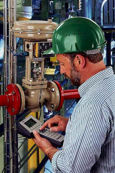
Fig. 1: Control valve with pneumatic actuator
When a fire breaks out, the fail-safe position of the pneumatic actuator will be adversely affected. The high temperatures cause the springs to lose their force. With increase in time and temperature, the springs can no longer keep the valve in its fail-safe position. In the case of “Fail-close“ action, increasing leakage cannot be avoided.
Fig. 2 shows how a preloaded spring loses its force under the influence of time and temperature.
Fig. 2: Force - temperature - time - diagram, loss of spring force
Shortly after the fire has broken out, the spring force decreases considerably. As a result, the ability to keep the valve in its fail-safe position during the fire will be lost within a short period.
The loss of rigidity and the considerable decrease of force are caused by recrystallization processes within the material structure of the spring.
The use of conventional fire protection systems, such as coatings, do not provide decisive advantages since springs are moving components and subject to dynamic stress. Coatings cannot sufficiently retard the loss of force either.
Safety cartridge
The problems discussed above were addressed by developing a thermostatic system. This passive system was designed to recognize non-typical temperature rises and respond to them actively. A quite simple cartridge element, was developed to perform this task.
This cartridge consists of two metal cylinders sliding freely within each other. It is filled with intumescent material which is composed in such a way that it reacts on reaching the release temperature, within certain boundaries, and then increases the force it exerts.
Fig. 3: Schematic of safety cartridge
The cartridge is made up of a two-piece cylindrical case. The enclosed cylindrical chamber contains the intumescent material. This material is composed in such a way as to ensure activation of the cartridge before the diaphragm of the pneumatic actuator is destroyed by high temperature. The increase in volume causes the cylinders to move in opposing directions. During this process, considerable forces are developed. The operating direction of the cylinders corresponds to that of the springs, thus opposing their gradual loss in strength. Installed in actuators with safety equipment [5], these patented cartridges compensate for decreasing spring force.
Fig. 4: Force of the safety cartridge increasing over time; after heating in accordance with the unit-temperature curve
The safety cartridge is heated according to the unit-temperature curve in which the development of temperature over time is plotted in accordance with DIN 4102, Part 8 [6].
Fig. 5: Unit-temperature curve
Installation
The design of this irreversibly operating cartridge is simple and allows retrofitting into already installed pneumatic actuators.
To do this, the safety cartridge must be installed in the center of the actuator springs. The mounting position of the pneumatic actuator is not important, the cartridge can always perform its task of closing the valve in the event of a fire.
The selected overall length of the cartridge does not affect the travel or operating range of the springs at standard ambient temperatures. Only in the event of a fire does the cartridge become effective, reacting to the unusually high temperatures.
Fig. 6, a: Arrangement of cartridges in the pneumatic actuator (sectional drawing) Fail safe, shaft extends.
a) Actuator springs “fail-close“; safety cartridges in deactivated state
b) Safety cartridges after temperature rise
Fig. 6, b: Arrangement of cartridges in the pneumatic actuator (sectional drawing) Fail safe, shaft retracts.
a) Actuator springs “fail-open”; safety cartridges in deactivated state
b) Safety cartridges after temperature rise
Simulation of a fire
A control valve equipped with a safety cartridge was subjected to a simulated fire test.
Technical data of the control valve used in the simulation:
|
Valve: |
SAMSON, Type 3241, nom. size DN 25, nom. pressure PN 40 |
|
|
Characteristic: |
equal percentage |
|
|
Valve plug: |
lapped-in-metal |
|
|
Plug material: |
Cr steel, WN 1.4006 |
|
|
Seat material: |
Cr steel, WN 1.4006 |
|
|
Body material: |
GS-C 25, WN 1.0619 |
|
|
Actuator: |
SAMSON, Type 3271 Pneumatic Actuator |
|
|
Effective diaphragm area: |
350 cm² |
|
|
“Actuator stem extends” |
||
|
Signal pressure range: |
0.6 to 3 bar |
|
|
Material: |
St 1203 |
|
|
Diaphragm: |
NBR with polyester fabric |
|
The test aimed at maintaining the tightness of the valve over 30 minutes minimum with constant system pressure acting on the valve. The time span is based on the specifications given in BSI 6755/2 [7].
The test valve described above was heated in a test oven according to the unit-temperature curve. The pneumatic actuator was equipped with 6 cartridges installed in the actuator spring assemblies.
The valve contained water. During the heating phase, steam was produced. A pressure regulator installed outside the test room maintained a constant system pressure of 30 bar. Prior to starting the test, a pump had been used to produce this pressure. Downstream of the seat/plug restriction area, the valve was open to atmosphere.
The temperatures in the test oven and at the pneumatic actuator were measured via thermocouples.
The temperature increase over time in the test room and in the pneumatic actuator was correspondent to the unit-temperature curve (see Fig. 5). The system pressure of 30 bar in the valve upstream of the seat remained constant during the entire test procedure.
Fire Test Summary
As expected, the rubber diaphragm was completely destroyed at the end of the test. With the exception of the springs, none of the metallic components showed any visible damages or deformations.
The task, to provide tight shut-off against the 30 bar pressure throughout the test during the high temperatures of a fire, was fulfilled for the entire period of high temperature supply.
Reversing operating direction
Apart from safety cartridges, there are additional solutions that can be integrated in the pneumatic actuator for safety.
Where a valve may normally be required to “fail open”, it is possible to use a preloaded spring assembly released at a pre-set temperature to oppose the standard fail-safe position.
This patented method [8] is composed of preloaded spring discs which act in opposition to the standard actuator springs. Upon release of the spring discs, the standard fail-safe action is reversed.
The spring discs are bound together by a solder strip. The selection of the type of solder determines at which temperature the spring discs are released to act as an additional safety device. The solder joint is extremely stable under practical operating conditions, such as permanently increased ambient temperatures.
A pneumatic actuator equipped with such a safety device is presented in the sectional drawing below.
Fig. 7: Sectional drawing of a pneumatic actuator whose standard fail-safe action (shaft extends) is reversed in the event of a fire. The release temperature range of the spring discs bound by a solder strip depends on the kind of solder selected.
Summary
The safety equipment detailed here are simple systems, enabling the pneumatic control valve to maintain, or to reverse, the fail-safe position upon outbreak of fire. Pneumatic control valves could now be used in fields of application not previously considered possible.
Safety Cartridges:
Compared to pneumatic control valves with standard fail-safe action, actuators equipped with these innovative safety devices are able to maintain the fail-safe position over an extended period of time when exposed to fire.
The safety cartridge filled with intumescent material plays an essential role in this safety technique. Thanks to these cartridges, the valve trim remains effective even at the extremely high temperatures of a fire, thus preventing leakage of potentially hazardous media or loss of product. The cartridges compensate for the loss in force of the springs, which under normal conditions guarantee fail-safe action.
Another asset of this system is its cost-effectiveness compared to other safety equipment in use. Since the use of safety cartridges can replace more complex and expensive safety devices or additional fire shut-off valves, they will prove to be another counter to increasing costs.
Reversing Fail safe units:
With this system, conventional fail-safe action can be reversed when a fire breaks out. The release of preloaded and bound spring discs reverses the direction of the standard fail-safe action of pneumatic actuators. An important aspect of this method is the fact that the temperature range at which the springs are released can be pre-selected as needed.
In view of all the advantages of the modern safety equipment developed by SAMSON, the use of pneumatic control valves could now be considered even where sensitive applications are concerned.
Bibliography
- Schneider, W. 1992. Der Metallbalg, ein zuverlässiges Dichtelement in Stellgeräten. In Chemietechnik, No. 3: 54-60.
- Schneider, W., and Bartscher, H. 1988. Stellgeräte im Rütteltest. Chemie-Anlagen-Verfahren, No. 8: 84-90.
- Kiesbauer, J., and H. Hoffmann 1998. Verbesserte Prozeßzuverlässigkeit und Wartung mittels digitaler Stellungsregler. Automatisierungstechnische Praxis, Vol 40, No. 2: 22-34.
- Vogel, U. 1991. Trends in der Stellgeräteentwicklung. Chemie-Anlagen-Verfahren: 59-62.
- SAMSON AG. 1994. Stellantrieb mit Sicherheitseinrichtung. Patentschrift DE 42 39 580 C2.
- DIN 4102, Brandverhalten von Baustoffen und Bauteilen.
- BSI 6755/2, Testing of valves, Part 2 1987. Specification for fire type-testing requirements.
- SAMSON AG. 1997. Pneumatisch betätigbare Antriebseinheit. Patentschrift DE 196 49 440 C1.