
Choke Valves
Go to Specific Subject: Choke Valve General Information | Choke Valve Design Specification | Choke Valve Maintenance and Inspection | Common Choke Valve Problems and Solutions | Choke Valve Papers and Applications | Subsea Choke Valves | Choke Control Systems
Choke Valve General Information
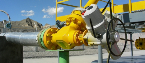
Choke Valves are severe service valves which are designed specifically for oil and gas wellhead applications, both in a surface and subsurface context. They are used for controlling the flow on production, reinjection and subsurface wellheads. Choke Valves are subjected to typical wellhead extreme conditions which can cause erosion, corrosion and other damage. Typically this can include high fluid velocity, slugging, sand production and multiphase of oil, gases and water. Also a Choke Valve has to have a very high turndown capability as it has to cover a wide range of flowrates. Thus the design of Choke Valves is required to be very robust with careful selection of valve configuration, flow path profiles, materials and ease of maintenance.
In subsea applications the Choke Valve has to cope with severe marine environmental conditions and be designed for subsea robot maintenance. If choke valves are selected poorly maintenance becomes a real issue with valves having to be removed regularly which is a real cost impost. Chokes can be operated manually or automatically. Sometimes a "choke bean" size is detailed, this is a device placed in a choke line that regulates the flow through the choke. Flow depends on the size of the opening in the bean; the larger the opening, the greater the flow.
Actuator selection is also important, actuators may be a "stepping type" or linear depending on the valve design. Control systems can be complex on large facilities where multiple wells are controlled to production and reinjection manifolds.
Choke Valve Design Specification
A typical Choke Valve Design Specification should include but is not limited to;
-
Process Data - Gas and Liquid Flow Rates (Including initial start up, Max flow for the life of the well), Production Profile over the life of the well, Wellsteam Composition, Fluid Type (eg., Natural Gas, Crude Oil, Condensate), Water, Fluid State (eg., oil), Compressibility. Design Pressure, Pressure Inlet and Outlet, Pressure Drop, Liquid Density, Design Temperature, SG, Vapour Pressure, Critical Pressure, Molecular Weight, Specific Heat Ratio, H2S content, Sand content and Actuator Sizing Differential Pressure. When selected the vendor should be requested to advise the Calculated Cv of the valve, percentage opening for the Cv selected for the Flow rates specified and predicted noise of the valve.
-
Mechanical Requirements
- Body - Inlet and Outlet size and ratings, body type (eg., angle), Rated Pressure and Temperature, Standard (eg., API 6A), Materials, NACE Requirements, Bonnet requirements.
- Trim - Size, Design, Flow Direction, Material for trim, stem, plug and seals, Leakage class, Maximum allowable noise.
- Actuator - Type, Air/Hydraulic, Operating medium pressures, Failure Mode, Actuator torque, Orientation, Stroke and Stroking Time and Limit stops.
- Positioner - Positioner type (eg., Pneumatic, Hydraulic, Electric), - Input signal, Output Pressure, Tube fittings, Material and Cable Entry.
- Accessories - Handwheel, Limit Switches, Pressure Trip Valve, Position Indicator, Filter Regulator, Volume Tank.
-
Special Notes - In Marine locations selection of materials should take the local environmental conditions into account as considerable corrosion can result from poor choices. This is particularly relevant for instrument fittings, tubing, positioners (feedback arms etc), actuator materials (especially in the case of pneumatic which "breathe", in which case "closed loop systems should be considered). Also for Hydraulic Systems the cleanliness of the hydraulic oil and system must be addressed at the design and maintenance stages.
Choke Valve Maintenance and Inspection
As Choke Valves are subject to severe service operating conditions they are not a 'fit and forget' component. Maintenance must be carried out in accordance with manufacturer's requirements. Inspection for erosion and corrosion of the body and components is critical and it is important that a failure mode effect and criticality analysis (FMECA) is carried out along with a rigid maintenance program based on fault analysis. Also if process conditions change for some reason, for example increased sand production then the maintenance and inspection "clock" must be reset to a period that is in line with the changed parameters. Note the use of predictive techniques such as sand monitoring and flowline erosion probes is useful but should not be used as a reason for reducing maintenance periods. This can only be achieved by comprehensive Choke Valve inspection and based on the result the "proof testing" and maintenance period then determined.
Common Choke Valve Problems and Solutions - Thanks to Mokveld
Corrosion
Corrosion is generally associated with the choice of wrong materials. A common mistake is to use a choke valve specification based on history. It must be remembered that an oil/gas well has a process component make up that is associated with a particular well. One well may produce Carbon Dioxide, while the other doesn't. A standard specification may cause the wrong material to be selected for an application. Corrosion is relatively easily solved, as a choice of suitable materials is widely available. However a comprehensive knowledge of materials is required as combinations of certain materials may lead to galling.
Erosion
It is important to understand the difference between single and two phase scenarios.
Velocity can cause body erosion, trim erosion and piping erosion. There are different philosophies with respect to what velocities are and not acceptable, however generally selected velocities are too high. For liquid application, a rule of thumb is that the velocity has to be controlled below 5-7 m/s measured in the outlet of the flange, for two phase this is 10-15 m/s and for gas 25 - 40 m/s. It should be noted that these figures do not include for sand production and also do not take the gas/liquid ratio into account for two phase situations. It should also be noted that often choke valves are reduced in size, for example a 4 inch nominal body with 6 inch inlet and/or outlet flanges. If the velocity at the outlet flange is still within the above mentioned rule of thumb it does not automatically indicate that everything will be expected to work out, as the velocity in the so called nominal body goes up and may well exceed what is considered to be acceptable. The choke velocity should be calculated first of all with the same body and flange size before reducing the nom body size. If the velocity is lower than mentioned in the above rule of thumb, one can calculate a smaller nominal body with smaller flange. If still within the given limits a smaller body with larger flanges can be used with reduced risk of erosion.
Thus velocity is the most important design criteria, correct design limitation of this in combination with a well-designed trim will limit any erosion.
Calculating velocities has to be based on general calculations for gas, liquids and a combination of the two (two phase). A calculation is required to determine the required Cv and this can be achieved by fitting different trims in nominal body sizes. However different pipe diameter selection produces different velocities. Relatively low velocities are not advised, as the result is likely to result in the selection of a too large size choke. High velocities are likely to result in erosion of the body with an associated high maintenance cost.
Trim selection is also very important. As an example Mokveld chokes are equipped with a cage provided with holes uniformly distributed over the full circumference. This design ensures that the fluid is symmetrically distributed. The many flow jets are diametrically opposed. Consequently, the energy is dissipated in the centre of the valve. This occurs in the fluid itself and not near the surface of any choke component. Also, preferential flow, the major cause of body erosion, is fully avoided.
Cavitation
Cavitation should not be taken lightly as it can not only lead to erosion but it can also cause vibration. The vibration may shatter brittle materials as Tungsten Carbide often used for the trim.
Leaking
Leaks on Choke Valves are sometimes caused by the selection of incorrect materials, but may be also attributed to general design of the Choke Valve. Some chokes have a split body design, these vary from a forged block (main body) with weld on or fitted flange connections (adapters) to main body bolted bonnet type. A one piece body casting is one answer to these problems. Also the Choke Valve seals have to fail before leaks occur. Seals utilised on almost all designs are of the ‘O'Ring’ type. As a choke is used under high pressure and pressure drop these O'Rings may be subjected to explosive decompression. This can cause them to split or deform. Should this happen the sealing property is lost. Explosive decompression often occurs when Viton is used. This happens to be one of the most suitable resilient materials for hydrocarbon service. Hence careful consideration of seal materials is required if Viton is selected as it is subject to explosive decompression. Furthermore the service of the O'Rings has to be considered as this can differ from static to dynamic applications. Most problems with O'Rings occur in dynamic applications.
Choke Valve Papers and Applications
The following technical papers, articles and application examples are from Mokveld.
|
Angle Choke Valves in China - Gas production well with API 15 000 Angle choke valves. |
Axial Choke Valves in Norway - Special choke valve used where space is limited on an FPSO. |
Angle Choke Valve - Versatile Heavy Duty Valve for Severe Applications - This comprehensive technical bulletin covers angle choke design, how fluid velocity is controlled with improved flow path design, how costs are reduced, the advantages of a cage guided piston, high rangeability, the safety bonnet feature, low emission and fire safe design, the FloSafe® bean, actuators and accurate control along with ease of maintenance features and a discussion on materials.
Angle Choke Valve - With the introduction of this new choke valve, Mokveld once again sets the benchmark for production uptime. Based on the Total Velocity Management® concept, choke erosion has been reduced by a factor of 4. This product specification covers the advantages and shows the various operating features of this Choke Valve. Also detailed are suitable Intelligent Positioners.
Mokveld Choke Valves, a Concept that Works - Chokes are critical for the safe and economic production of the world’s oil and gas reserves. In the past simple needle-and-seat chokes were adequate as pressure cuts were low and the applications of adjustable chokes were less demanding. Also, in that era, adjustable chokes employing the rotating disc principle provided satisfactory performance. A number of factors have changed the demands on chokes. Operating pressures have increased. Safety and reliability are becoming increasingly important. And ?nally, the economics of the equipment, seen over the life of the ?eld, are vital for the pro?table development of the ?eld. The new challenge was met by Mokveld with a proven expertise in control valves. Mokveld pioneered in the use of cages in production chokes. A cage-type choke has a multiple-ori?ce cylinder - the cage - and a piston which is connected to the stem. The movement of the piston modulates the area of the ?uid passage. As a result of the impingement effect generated in the cage-type design, the erosive action of the ?uid is fully under control. Also, noise is reduced to safe levels.
Subsea Gas Compression with Mokveld Subsea Control Valves - Subsea gas compression is a technology approach that can boost recovery rates and lifetimes of offshore gas fields. Aker Solutions - at the forefront of subsea gas compression - was awarded the contract by operator Statoil to supply a complete subsea compression system for Norway’s Åsgard field. The project represents a quantum leap in subsea technology, and an important step in realising Statoil’s vision of a complete underwater plant.
Links to Other Choke Valve Technical Papers and Articles
New Choke-Valve Design Improves Separator Efficiency - Marco Betting - Hugh Epsom - A new type of choke valve that improves the efficiency of downstream gas/liquid separators by enhancing the coalescence of dispersed liquids in a fluid stream has been developed recently by Twister. The initial field test of the technology, known as the SWIRL valve, was performed at a JT-LTS production unit operated by NAM in the Netherlands. The test demonstrated that the replacement of a conventional JT valve with the coalescing choke valve resulted in a significant improvement in the dew pointing performance of the gas-processing facility - from Twister.
Slug Control of a Production Pipeline - Tormod Drengstig and Sissel Magndal - This paper presents the results of a simulation study on a production pipeline at one of Statoils installations in the North Sea. Due to low flow rate, there is a slugging problem in this pipeline. The aim of the study has been to simulate different control structures in the multiphase flow simulation tool OLGA in order to suppress slugging. The main result from this study is that the slugging problem for the investigated pipeline is completely suppressed using a pipeline inlet control strategy with a simple PID controller. The controlled variable in all cases is the topside choke valve opening, and the measurements are pressures at different locations of the pipeline - from www.scansims.org.
Well Heads, Chokes and SSSVs - Chokes hold a backpressure on a flowing well to make better use of the gas for natural gas lift and to control the bottomhole pressure for recovery reasons. In vertical pipe flow, the gas expands rapidly with decreasing hydrostatic head and the liquid moves in slugs through the tubing. The potential gas lift energy is rapidly lost and liquids fall back and begin to accumulate over the perforations. Accumulating liquids hold a back pressure on the formation. If enough liquids accumulate, the well may "die" and quit flowing. A choke holds back pressure by restricting the flow opening at the well head. Back pressure restricts the uncontrolled expansion and rise of the gas and thus helps keep the gas dispersed in the liquids on the way up the tubing - from George E King Consulting Inc.
Technical Recommendation for Production Chokes - This technical recommendation covers Valve Design, Body Design, Trim Design, Valve Actuation and provides an example Choke Valve Data Sheet - from Masterflo.
The following links are from CCI.
-
Technical Recommendations for Choke Valve Specifications - A typical choke valve specification, whilst based on CCI's Drag technology design it is still useful in putting together a specification.
-
Prolonging Choke Valve Life - The life of choke valves has typically been unacceptably short. Multistage valve technology has been shown to prolong their life by as much as 10 times.
-
Technology for Severe Service Choke Valves - This technical bulletin has some good technical information in regards to severe service chokes.
Subsea Choke Valves
|
ICEweb needs more technical papers on Subsea Choke Valves - so if you have some please pass them on. |
The following technical papers, articles and application examples are from Mokveld.
Subsea Choke Valve - Mokveld has developed a Subsea control valve which further enhanced their knowledge about sealing technology. They have extensive expertise in the field of material selection and flow management. This expertise delivers new choke valve technology. A full-scale sand erosion test of the newly developed choke valve has confirmed a significant improvement in erosion resistance. Based on its growing expertise of materials and flow patterns, and in close cooperation with customers and third party organisations, Mokveld continued to improve its angle choke valve designs using the Total Velocity Management® (TVM) design concept and advanced tools such as Finite Element Analyses and Computational Fluid Dynamics. A new generation choke valve, the TVM angle choke valve, is the result. Full-scale sand erosion tests confirmed a significant improvement in erosion resistance. The erosion of this new angle choke valve was reduced by factor 4 compared to conventional designs.
Subsea Axial Choke Valve - The newest topside technology is also available for subsea applications now. Due to the high capacity and large sizes, these valves are ideal for high flow wells and the axial flow design eliminates the possibility for cage collapse.
Links to Other Technical Papers and Articles:
Subsea Choke Valves meet Gulf of Mexico HPHT Challenges - Jeff Colbert - Tough operating conditions have required critical performance by subsea choke valves installed in deepwater, HPHT conditionsat GOM development projects - from Masterflo.
Stabilizing Slug Control Using Subsea Choke Valve - Mats Lieungh - This Thesis studies the possibility of riser slugging control in offshore production using a subsea choke valve - from NTNU.
Choke Control Systems
Electric Subsea Controls Coming of Age - A “plug and play” philosophy has been adopted in FMC’s electric system so actuators can be added and/or retrieved by an ROV during the engineering, testing, and operational phases without requiring any specific engineering. This also means valve actuators can be repaired using an ROV. The electric system’s redundant control modules are retrievable individually so the system can be repaired without shutting down the well. This improves on traditional electro-hydraulic systems, which normally contain the redundancy within one large control module and require well shutdowns during repair and retrieval.
|
ICEweb needs more technical papers on Subsea Control Systems - so if you have some please pass them on. |