
Intrinsic Safety, Barriers and Isolators
|
Intrinsic Safety (IS) uses the concept of limiting the amount of energy at the Hazardous Area so that it is incapable of ignition. Appropriately designed Intrinsically Safe devices depending on their certification can be used in all zones and are categorised as;
ISA-RP12-6 defines intrinsically safe equipment as "equipment and wiring which is incapable of releasing sufficient electrical or thermal energy under normal or abnormal conditions to cause ignition of a specific hazardous atmospheric mixture in its most easily ignited concentration". Intrinsically Safe Instrumentation and the associated systems are usually allocated a Gas Group IIC classification, this means they are suitable for all Gas/Air mixtures. |
Most IS Instruments achieve a T4 (135 deg C) which satisfies all industrial gases except Carbon Disulphide.
Because standard Instrument Cables can be used, no conduit and bulky enclosures are required the concept is the most cost effective.
One of the largest advantages of IS is that the systems can be worked on live without a hotwork permit, however test equipment must also be IS certified.
There are a proportion of engineers who select Exd (Flameproof) or Exn (Non Incendive) equipment because they see IS as being too hard to design, install and maintain, however this is a false premise as concept is the most effective method of ensuring electrical safety in the hazardous area. Actually the correct installation and ongoing maintenance of the alternative concepts (Exd, Exn, Exe etc) require more care and maintenance over the life of a facility.
The Intrinsically Safe Equipment Certificate is a very important document in that must be utilised in all phases of the facility life, hence it should be kept in a readily available Ex Equipment Dossier. It has details of design and installation requirements such as cable parameters and other specific provisions for the equipment. Each piece of IS equipment carries a certification label which designates the Ex category, Gas Group and Temperature Rating.
Exd , Exn or other certified equipment must not be used in a IS circuit! There are some devices that are designated "simple devices" for example a switch, these do not require certificates.
A very important issue in working with Ex is Personnel Competency in the Design, Installation and Maintenance of Electrical Equipment in Hazardous Areas. There are many competency based courses available around the world and it is Essential that anyone involved in these areas are assessed and accredited to work on any Ex system. This competency should be reassessed every three years at a minimum.
Intrinsic Safety - The Fundamentals
Intrinsic Safety in a Nutshell - David Hohenstein - Intrinsic safety is the safest, least expensive, and easiest to install method of protection available. These safety systems offer significant labour savings over traditional protection methods because there are no heavy conduits or bolted enclosures. Material costs are less because a standard enclosure is the only major expense for mounting the barriers. So, how does it work? - from Pepperl and Fuchs.
Intrinsic Safety Basics - Paul S. Babiarz - Making instruments intrinsically safe need not seem like a nightmare. Here, the basics of intrinsic safety circuit design are discussed - from Omega.
Intrinsic Safety Basic Principles - A quick guide from GM International.
Intrinsically Safe Design
AN9003 A User's Guide to Intrinsic Safety - This guide from MTL is a really excellent reference.
Engineers Guide - Process Automation Interface Technology - This Engineer's Guide is much more than just a catalogue of data sheets and specifications: it also includes a technology section with information about the principles behind field signals, explosion protection and functional safety. Appropriate application examples illustrate the main features - Go to page 37 for the Intrinsic Safety Section - This an excellent resource from Pepperl and Fuchs.
Uwhat? - Understanding I.S. Terminology - Covers Associated Apparatus, Output Parameters, Safety Description, Reactance Parameters, Field Equipment, Alternative Notations and Other Parameters - from RTK Instruments.
Protecting the I.S. System from Outside Influences - Covers Precautions, Capacitance, Surge Protection, Mechanical Protection and Cable Installations - from RTK Instruments.
Intrinsically Safe or Explosion proof - Understanding the Technology - The phrase “Intrinsically Safe” is often used generically to describe products destined for hazardous (explosive) areas. This paper explores the term “Intrinsically Safe”, provides an overview of what is required to certify a product and compares Intrinsic Safety against Explosion Protection concepts - from CorDEX Instruments.
Assembling an Intrinsically Safe System - Covers the Barrier System, Simple and Non-Simple Apparatus, Incomplete Parameters, System Category, Variations, Cables along with a simple logic table for the selection of the correct barrier or Isolator - from RTK Instruments.
Intrinsic Safety in Hydrogen/Oxygen Mixtures - Occasionally it is necessary to make measurements in hydrogen/oxygen mixtures. The increased use of fuel cells and the use of hydrogen as a vehicle fuel have increased the frequency with which this requirement occurs. The requirement occurs usually within process vessels since when the mixture is released the problem becomes a mixture of hydrogen/oxygen /air which is a slightly different problem. Conventional intrinsically safe equipment certified to the IEC standard is considered to be adequately safe under normal atmospheric conditions. The ATEX guidelines on the 94/9/EC directive state ‘A product within a potentially explosive mixture without the presence of air is not in the scope of the directive’. It follows therefore that that a safety analysis of an electrical installation in a hydrogen/oxygen mixture must be based on a risk analysis using the best available information. The conventional IS certification ensures a satisfactory level of construction but additional consideration must be given to the levels of voltage, current and power used. This note proposes an approach, which the author considers, achieves an acceptable level of safety.
How to Calculate an Intrinsically Safe Loop Approval - Gary Friend - We all know what can happen if the correct techniques are not used when interfacing into the hazardous area. Using intrinsic safety (Ex i based on IEC/SANS 60079-11; IEC/SANS 60079-25), the energy in the hazardous area is limited to below the ignition energy of the gas present, thereby preventing explosions - from South African Instrument & Control.
Associated Apparatus
Associated Apparatus is the equipment interfaces between field and control room equipment. These are usually Zener Barriers or Isolators which protect the Hazardous Area circuits by limiting the voltage and current in normal and under fault conditions. Zener Barriers or Isolators used in Intrinsically Safe circuits must be designed and certified as Associated Apparatus suitable for connection to the selected intrinsically safe or simple apparatus in hazardous Area. The Associated Apparatus is designed to achieve the maximum allowable safety parameters of the circuits connected the Hazardous Area terminals of the barriers. Associated Apparatus has slightly different identification than the field equipment because it is installed in the safe area. An example of this is [EExia]IIC , note the brackets, these highlight that the equipment must be mounted in the safe area.
Earthing and Bonding in Hazardous Areas
A Definitive Guide to Earthing and Bonding in Hazardous Areas. LC Towle - This document details what has proved to be acceptable practice for earthing and bonding of electrical apparatus used in hazardous areas. The subject is not complex, but partially because it is relevant to more than one area of electrical expertise a systematic approach to the subject is desirable. There are numerous codes of practice which specify how earthing and bonding should be carried out, but the fundamental requirements are independent of the geographic location of the installation and hence there should be no significant difference in requirements. This document predominantly describes what is acceptable prac tice in the United Kingdom and Europe. If a national code of practice exists and differs fundamentally from this document then it should be questioned. It may be considered expedient to comply with such a code but it is important to be assured that doing so results in a safe installation. Some parts of this note state what are well known basic principles to practising electrical and instrument engineers. They are restated primarily for the sake of completeness, and ease of reference - from MTL.
The Earthing of Zener Barrier Installations - Details Barrier Earth, Code of Practice, Practical Earth Connection, Making the Earth Connection, Cable Installations and Special Cases - from RTK Instruments.
Engineers Guide - Process Automation Interface Technology - This Engineer's Guide is much more than just a catalogue of data sheets and specifications: it also includes a technology section with information about the principles behind field signals, explosion protection and functional safety. Appropriate application examples illustrate the main features - Go to page 63 for the Earthing Section - from Pepperl and Fuchs.
Gases Classification Relative to Ignition Temperature
Subdivision of Gases and their Classification Relative to Ignition Temperature - These tables list gases which are subdivided by hazardous area classification according to ignition temperature and temperature class from GM International.
Hazardous Area Verification Dossier
Hazardous Area Verification Dossier - Australian Standards AS/NZS 2381.1:2005 and AS/NZS 61241.1.2:2000 state that a ‘Hazardous Area Verification Dossier’ shall be prepared for all electrical installations located in a defined hazardous area. AS/NZS 2381.1:2005 and AS/NZS 61241.1.2:2000, both state in part that, ‘It is necessary to ensure that any installation complies with the appropriate documents, this standard and any other requirements specific to the plant on which the installation takes place.’ A verification dossier shall be prepared for every hazardous area installation and kept on the premises. The dossier should contain the information detailed in the relevant Australian Standard for the type of protection concerned. This Installation Advice gives details on necessary content of the dossier - from Clean Energy Australia.
Intrinsically Safe Cables
Low voltage and current in intrinsically safe circuits allow the use of ordinary instrumentation cables provided that capacitance and inductance are taken into account in assessing the safety of the system. Cable parameters seldom are rarely a problem and long distances can be easily achieved. Generally Intrinsically Safe cable calculations are completed at the design stage, however really a good method is to review all the IS equipment certificates and determine the most onerous case and calculate the distance for that particular circuit plus devices. The Minimum Ignition curves along with the Equipment Maximum Cable Parameters and the Actual Cable Parameters are used in the calculation. Thus all the other circuits must then comply since they would give longer distances. Of course this must be documented in the IS Equipment section in the Hazardous Area Verification Dossier.
Cables for I.S. Installations - Covers Cable Parameters, Individual /Multicore Cables, Sheath Cover, Screens and Sheaths along with the need for Cable Segregation - from RTK Instruments.
Cable Parameters and All That - The intrinsically safe [IS] system standard [IEC60079-25] discusses in detail how to draw up the system documentation and in particular how to calculate the permitted cable parameters. Unfortunately the standard has to take into account all the possible variations and hence the process looks quite complicated. In the majority of applications the simple precaution of using a single source of power with no significant capacitance or inductance across its output terminals [Ci &Li] and field devices with only small input capacitance and inductance [Ci & Li] removes any problems - from MTL.
Engineers Guide - Process Automation Interface Technology - This Engineer's Guide is much more than just a catalogue of data sheets and specifications: it also includes a technology section with information about the principles behind field signals, explosion protection and functional safety. Appropriate application examples illustrate the main features - Go to page 62 for the Intrinsic Safety Cables Section - from Pepperl and Fuchs.
Junction Boxes
Thoughts on the Design of Intrinsically Safe Junction Boxes - Junction boxes are ‘simple apparatus’ when used in intrinsically safe circuits, and given a little thought they can make life simpler for the installation and maintenance engineer - from MTL.
Minimum Ignition Curves
Minimum Ignition Curves - The following graphs answer the question: What is a dangerous amount of electrical energy? These graphs are for circuits containing aluminium, cadmium, magnesium or zinc-substances that produce a high temperature incendiary spark. It is important to keep in mind that these curves reflect the worst case scenario. When designing intrinsically safe electronic equipment today, most manufacturers start by specifying the equipment for the worst possible case. The graphs chosen are those that are used most often by designers and manufacturers of electrical apparatus from GM International.
Simple Apparatus / Devices
These are passive components (switches, resistive sensors, potentiometers), simple semiconductor (LEDs, phototransistors) and simple generating devices (thermocouples, photocells) are regarded as Simple Apparatus if they do not generate or store more than: 1,5 V, 100 mA, 25 mW. Simple Apparatus can be used in Hazardous Area without certification; they have to be assessed for the temperature classification on the basis of the matched output power of the interface device.
Simple Apparatus - or not so simple? - Describes the concept of Simple Apparatus, Increased Scope, Distributed Inductance, Added Complications, Inviolate Assemblies, Care with Cables, Temperature Category and Limitations of Use - from RTK Instruments.
Zener Barriers and Isolation Devices
While a zener diode barrier is normally the most cost-effective solution, the intrinsic safety isolator using galvanic isolation is normally the superior, long-term performance solution. This is because galvanic isolation and the additional electronics used within intrinsic safety isolators provide better noise immunity, signal conversion options, application-specific designs, no intrinsic safety ground connection/maintenance requirements, signal enhancement, logic control features, and fewer impedance concerns. The term galvanic isolation is often linked to and identified with an intrinsic safety isolator. This is because intrinsic safety isolators use galvanic isolation components such as transformers, relays, and capacitors. Both the zener barrier and IS isolator are used to provide energy limitation to circuits/components mounted in hazardous ‘classified’ locations. Since these hazardous locations are ignition capable, it is important to provide a reliable means of limiting energy that can be transmitted so an explosion hazard is not created during normal or fault operation of the circuit. So, the decision to use an intrinsic safety isolator (galvanic isolation) or zener barrier really comes down to the application - from Pepperl and Fuchs.
The following is from the excellent publication South African Instrument and Control; A Zener barrier is a simple device where the voltage is limited by a Zener diode and the current by a resistor. A fuse is present to protect the Zener diode as shown in Figure 1. The key to safety is the intrinsically safe earth. Without it, there is no protection. If the input voltage increases above Zener diode voltage, the Zener conducts and the fuse blows, after which the Zener barrier needs to be replaced. In addition, the barrier has a volt drop across it under normal operating conditions, so careful calculation must be done to ensure that there is sufficient voltage at the field device. [Note: using Zener barriers without an IS earth is not safe.]
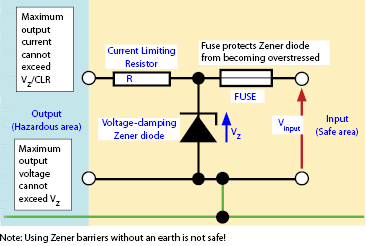
Figure 1.
Galvanic isolator
A galvanic isolator is an active device that energy limits without the dependence on the IS earth for safety as shown in Figure 2. It also has the advantage of supplying higher voltage at the hazardous area terminals and allowing longer cable lengths. Isolators have local LED indication and most 4-20 mA isolators transfer Hart communications through the optical isolation.
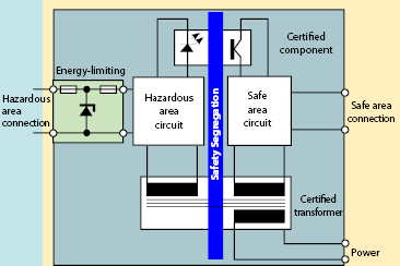
Figure 2.
Engineers Guide - Process Automation Interface Technology - This Engineer's Guide is much more than just a catalogue of data sheets and specifications: it also includes a technology section with information about the principles behind field signals, explosion protection and functional safety. Appropriate application examples illustrate the main features - Go to page 57 for the Intrinsic Safety Zener Barriers and Isolator Section - from Pepperl and Fuchs.
Zener Barriers or Isolation Interfaces? - Covers Types of Interface, Earthing, Insulation Requirements, Discharge Path, Zone 0 Installations, Supply Voltage Tolerance, Power Requirements, Dissipation, Application Flexibility, Accuracy, Response, Reliability, Security along with a comparison table - from RTK Instruments.
Intrinsic Safety Applications
Load Cell Intrinsically Safe Installation Application Note - When the weight indicator or digitiser is not Intrinsically Safe it may not be placed in a Hazardous Area. However, strain gauge load cells are inherently passive devices and ‘safe’. (Although long cables may exceed capacitive and inductive limitations ~ a barrier to load cell cable length of 100m is usually no problem; other limitations not withstanding). So load cells may be placed in the Hazardous Area so long as the power delivered to them is strictly limited under any fault condition. Shunt Diode Safety Barriers are used to limit the power to safe levels, but their use must be according to approved safety practice - from Ian Fellows Ltd
Intrinsically Safe Fire Protection Devices -The need for safety in potentially explosive atmospheres where electrical devices are used has increased substantially over the past several years. Today, applications for intrinsic safety abound in virtually every industry. The purpose of this guide is to provide general information on intrinsic safety and fire protection in hazardous areas - from System Sensor.
Intrinsically Safe Mobile Phones and Other Neat Devices - The following websites are worth a look.
ECOM Mobile Safety
i.safe Mobile
PIXAVI
Questions on Intrinsic Safety or Ex equipment? See ICEweb's Electrical Equipment in Hazardous Areas Technical Information Page.
Looking for Intrinsic safety in Fieldbus Systems? See ICEweb's Fieldbus page.
For Information on Selection, Installation and Maintenance of Electrical equipment in Hazardous Areas and other protection concepts + HA Classification see ICEweb's Electrical Equipment in Hazardous Areas Technical Information page.
The following are from the South African Flameproof Association
- Cost Comparison of Methods of Explosion Protection
- Comparison of the Techniques of Intrinsic Safety ‘ic’ and Energy Limitation ‘nL' - Some years ago [2002?] a decision in principle was made by the IEC committee TC31 to discontinue the energy limited technique from the Type’n’ standard IEC 60079-15 and transfer the responsibility for this safety technique to the intrinsic safety [IS] sub-committee. This was largely because the relevant expertise was available within the IS committee and the change coincided with some thinking on the application of categories of safety to hazardous area equipment. This decision is now feeding through the system as the ‘ic’ technique. It is embodied in the current issue of the apparatus standard [IEC 60079-11] the CDV of the system standard [IEC 60079-25] and the FISCO standard [IEC 60079- 27]. The next edition of the IEC code of practice [IEC 60079-14] contains a useful guide to the corellation between the three levels of protection and the recently introduced concept of ‘Equipment Protection Levels’ [EPLs]. The ‘nL’ concept is dealt with in one sentence “Energy-limited circuits ‘nL’ shall comply with all the requirements for intrinsically safe circuits ‘ic’” The basic principle remains unchanged, that is to create a system which is intrinsically safe in ‘normal operation’. Normal operation includes open circuiting and short-circuiting of field wiring so as to permit ‘live working’. In addition there are some construction requirements so as to ensure a reasonable level of integrity. The situation is slightly confused because the North American practice is to use ‘non-incendive’ apparatus in Division 2, which is almost the same as ‘nL’ apparatus but not quite. The major difference is that ‘non-incendive’ apparatus uses a factor of safety of 1,1 on the usual IEC ignition curves whereas the ‘nL’ standard and the ‘ic’ requirement is a unity factor of safety. This means that ‘ic’ and ‘nL’ apparatus may not meet the requirements of ‘non-incendive’ apparatus although in the majority of cases it does. The use of cadmium discs and the most easily ignited mixture of gases within the test apparatus are considered to ensure an adequate factor of safety for Zone 2 purposes. This change in safety factor means that the available power in ‘ic’ circuits is greater than that in other IS circuits. It is important to recognise that the significant effect of the change to ‘ic’ is that the application of this equipment is clarified but there is no intention to modify the fundamental principle. The remainder of this note highlights the areas where this clarification is effective. In the past the absence of positive guidance enabled individuals to make decisions, which they considered adequately safe. Some more expert practitioners will regret the loss of this flexibility. Possibly the ‘non-incendive ‘technique will live on for some time because of this factor.
Shunt-Diode Safety Barriers and Galvanic Isolators - a Critical Comparison - The discussion on the relative merits of galvanic isolators and shunt diode safety barriers has been carried on for many years. The majority of other articles on this subject have aimed to prove the superiority of one technique over the other. This paper brings together the illustrations which have accumulated over a considerable time in response to various questions raised at presentations. It attempts to make balanced arguments so that the reader can decide the most suitable technique for a particular application. It ends with a score sheet which might be found useful if a decision is not completely self-revealing - from MTL.
Intrinsic Safety - The Appropriate Technique for Zone 2 - L C Towle - Concern for safety, economy and ecology has led to progressively more effective steps being taken to reduce the possibility of significant leakage of flammable substances on all types of petrochemical plant. As a consequence, the major part of most potentially hazardous plants are now designated Zone 2. In practice, if large areas of a plant are designated as Zone 0 or Zone 1 then inspection authorities are likely to ask if all reasonable measures have been taken to minimise leaks. This tendency to classify the major part of the plant as Zone 2 naturally suggests that the precautions considered necessary for the use of electrical equipment can be relaxed, and the possibility of using type ‘N’ equipment naturally follows. This document explains why, in the particular case of process control instrumentation, this apparently logical progression is not a sound idea and why intrinsic safety is still the preferred technique - from MTL.
Intrinsic Safety in Fieldbus Systems
FISCO Intrinsically Safe Fieldbus Systems - This application note is a practical guide to the selection, installation and maintenance of equipment complying with the Fieldbus Intrinsically Safe Concept (FISCO). The document begins with a discussion of the origins of FISCO and an introduction to the main elements that should be considered when assembling FISCO systems. Later sections then develop each subject in more detail, with the intention of providing clear guidance to new and experienced fieldbus users - from MTL.
Surge Protection for Intrinsically Safe Systems - This publication discusses the nature of the threat to intrinsically safe instrumentation in hazardous areas from voltage surges induced by lightning or other causes. The practical application of surge protection devices (SPDs) is also considered taking into account the certification/approvals requirements.
Intrinsically Safe Fieldbus In Hazardous Areas - Armin Beck - Decision Guidance for Intrinsically Safe Fieldbus Solutions - Currently different solutions are available for intrinsically safe fieldbus like Entity, FISCO or High-Power Trunk and recently announced redundant FISCO and DART concepts. This paper chronologically accounts the history of all intrinsically safe explosion protection concepts for fieldbus and gives an outlook on DART and the redundant FISCO concepts. The paper then goes on to compare all methods one-on-one with a practical view on their merits and drawbacks. This paper is directed at technical decision makers involved in planning fieldbus topologies for the hazardous area in search of solutions - from Pepperl & Fuchs.
DART Ushers in the Next Generation of Intrinsic Safety - In the process industries, fieldbus technologies have helped many process users to manage their assets intelligently based on the wealth of information that smart field devices can deliver. However, fieldbus in hazardous areas requires particular attention with regards to explosion protection. Here, power restrictions on equipment that limit the network device-count can make some installations cumbersome or difficult to realize. Since the advent of intrinsic safety (and later fieldbus), several concepts have addressed this problem with incremental success. Now, a new concept “Dynamic Arc Recognition and Termination (DART)” has eliminated the power problem while maintaining intrinsically safe energy levels of power supply, installation components down to the device with a new approach to energy limitation. The concept allows for considerably higher direct power, while ensuring intrinsically safe energy requirements via rapid disconnection - from Pepperl & Fuchs.
Dart - The New Dimension in Intrinsic Safety - Udo Gerlach, Thomas Uehlken, Ulrich Johannsmeyer, Martin Junker and Andreas Hennecke - Intrinsic safety is a worldwide accepted type of ignition protection, which offers many advantages over other types of ignition protection. The dynamically acting intrinsically safe energy supply concept DART is a means of facilitating considerably higher direct power, with simultaneous intrinsically safe energy limitation through rapid disconnection. This paper explains the principle of operation of DART as well as two areas of industrial application. It also illustrates the essential technical safety aspects necessary for the demonstration of intrinsic safety and explains the impact of these on the relevant international standards. In conclusion, practical areas of application in the process industry are examined - from Pepperl & Fuchs.
The New Dimension of Intrinsic Safety - Rick Ogrodzinski - Intrinsic safety type of protection is currently achieved by limiting the available power. This limitation of power - usually to less than 2 W - provides intrinsic safety (Ex i) and is therefore mainly employed in the area of control and instrumentation in the power supply to actuators and sensors with low connected load. A significantly higher direct power with the simultaneous safeguarding of all the positive characteristics of intrinsic safety offers the user a new and essentially wider scope of application. These aims are achieved through DART technology (DART: Dynamic Arc Recognition and Termination). DART is a means of instantaneous tripping, which dynamically detects an undesired condition or a fault in the electrical system precisely as it occurs and instigates an immediate transition to a safe condition before any safety-critical parameters are exceeded. DART is based on the detection of fault conditions and their characteristic rate of rise of current - from Pepperl & Fuchs.


