Safety Requirements Specification in a Capital Project Environment
Dr. Angela E. Summers, P.E., President, SIS-TECH SOLUTIONS, LLC
PMB-295, 2323 Clear Lake City Blvd, Houston, TX 77062-8032
713-320-4777 (phone) 281-461-8109 (fax)
Presented at the Texas A&M Instrumentation Symposium 2000
Submitted for publication in Control Engineering
Abstract
The safety requirement specification (SRS) is a new documentation requirement of the safety system standards. It must be developed during the execution of a capital project involving Safety Instrumented Systems (SIS). In both the US domestic and international standard, the performance and functional requirements are defined in the SRS. These requirements provide the key measure by which the SIS design is compared and judged throughout the remainder of its lifecycle. Therefore, it is important to understand the contents, ownership, and appropriate timing of the SRS. Once understood, the project work breakdown can be modified to include this key deliverable in the execution of the SIS lifecycle. This paper will propose how to overlay the SRS deliverables with a typical project implementation cycle.
Introduction
The development of a safety requirements specification (SRS) is an important step in the safety instrumented system (SIS) lifecycle, presented in the US domestic and international SIS standards. All phases of design are judged against the SRS.
Unfortunately, neither standard provides a clear purpose, scope, or timing of the SRS. According to ANSI/ISA S84.01-1996 1 and draft IEC 61511 2 :
- The objective of the SRS is " to develop specifications for safety instrumented systems design."
- The SRS can be a collection of documents or information.
- The SIS lifecycle is shown as a series of steps leading many engineers to believe
that the SRS is generated as a single deliverable after the process hazards analysis (PHA). Compounding the situation, neither standard provides clear differentiation between the SRS and typical capital project documentation. This has resulted in a wide assortment of responses to the SRS. Some companies are essentially doing nothing, assuming that the SRS is covered by current documentation. Others have created a comprehensive, new document that the design team must complete. And, of course, there are many in the middle, filling in the gaps in their current documentation with any new requirements.
To determine how the SRS is best developed, it is necessary to back up and take the "big picture" approach. Elements of the SRS are developed, modified, or utilized throughout the lifecycle. This means that the SRS is not a document generated at a single point by the project team, but it is instead a document that evolves throughout the entire design. While the SRS serves as the basis for the SIS design, it is substantially more than a "specification" for the SIS design. It is used as the primary validation tool for the SIS design and is the basis for on-going management of change activities.
The United States Occupational Safety and Health Administration (OSHA) Process Safety Management (PSM) program requires the compilation and on-going maintenance "process safety information." The purpose of the process safety information is the documentation of identified process hazards and how these hazards are being managed during plant operation. The content of the SRS is essentially the process safety information for safety instrumented systems.
The SRS establishes the safety functional requirements for the SIS. These consist of the logic and actions to be performed by the SIS and the process conditions under which the actions are initiated. The functional requirements specification includes the following general topics:
- Safe state of the process
- Process inputs and trip points
- Process outputs and actions
- Functional relationships, failure modes
- Manual shutdown and reset requirements
- Maintenance/bypassing requirements
- Response time requirements
- Human machine interface requirements
The SRS also includes the safety integrity requirements that document the risk reduction allocated to each independent protection layer. The safety integrity requirements for the SIS provides the safety integrity level (SIL) and performance required for executing each safety function 3 . A critical input to the safety integrity requirements is the assumptions concerning any other independent protection layers used for risk reduction. The SIS performance criteria must include common mode failures, diagnostics, maintenance, functional testing, and reliability issues.
Taking its content into account, the following project lifecycle steps are affected by the SRS:
- Feasibility
- FEL (front end loading)
- Design
- Validation
- Operation
- Maintenance
- Training
- MOC (management of change)
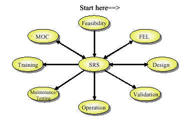
The effect of the SRS on each of these steps varies. For a typical grass-roots project, the interaction is illustrated below with the initial step being "feasibility" and continuing clockwise around the figure. The important point of this illustration is that the SRS is central to the design of the SIS. All activities associated with the SIS either affect or are affected by the SRS. Therefore, the SRS must be developed and reviewed by a team of people with process, equipment, operating, and maintenance experience and knowledge.
SRS Lifecycle
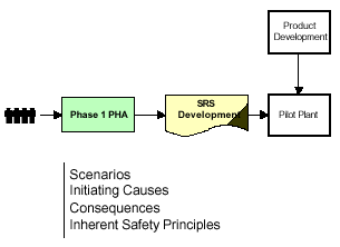
Starting with early feasibility studies, chemists and chemical engineers perform the research and development that is necessary to understand not only how to make product but also how to control the process. Potential incident scenarios are discussed, including the initiating cause of the scenario and the consequence. When building the pilot plant, these scenarios are used as the design basis for safeguards in the pilot plant. These safeguards often focus on the application of inherent safety principles to reduce the risk of the incident. If the residual risk is still too high, additional measures are taken, which typically include the application of independent protection layers. The lessons learned throughout the feasibility study process are critical inputs into the SRS.
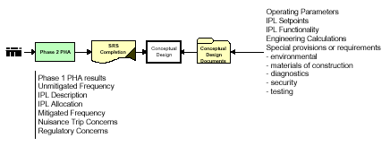
During front-end loading, the scenarios identified during the feasibility studies are examined, along with any other scenarios that the team may identify. After the examination of inherent safety principles, the unmitigated frequency of each potential incident is estimated. At this point, the risk associated with each incident is known and risk management decisions must be made. These decisions typically involve the use of passive protection systems (e.g. pressure relief valve), active protection systems (e.g. critical control systems and alarms or SIS), and consequence mitigation systems (e.g. fire and gas). Each of these protection layers is used to reduce the risk associated with each incident scenario to a tolerable level.
The SRS should include a description of how each of these protection layers are intended to function, including any assumptions made regarding their design integrity. Any special regulatory concerns, such as specific State or Government regulatory requirements or siting issues, should be documented. If nuisance tripping can cause cascade tripping of SISs in other units, this must be considered in the design basis.
Finally, the remaining SRS elements described in the standards in the safety integrity requirements and the safety functional requirements are developed as part of the basis of design specification or conceptual design. These elements include the following:
- Operating parameters
- IPL Setpoints
- IPL Functionality
- Engineering Calculations
- Special provisions or requirements
- Environmental
- Diagnostics
- Testing
- Materials of construction
- Security
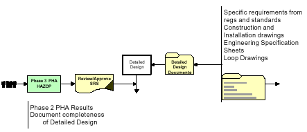
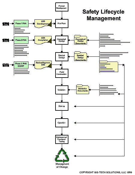
The detailed design is performed according to the conceptual design and the SRS. Any deviation from these documents should be evaluated to ensure that the risk reduction specified for each independent protection layer is not compromised. The detailed design documents include construction and installation drawings, engineering specification sheets, loop drawing, and procedures. When P&ID drawings are nearing completion, a HAZOP is typically performed to identify hazards or operability problems that could result in an incident. The draft SRS should be used to verify that all of these identified risks are mitigated to a satisfactory level. Thus, the HAZOP serves as a verification of the completeness of the design with respect to safety and the completeness of the SRS.
As described above, the development of the SRS for a grass roots facility occurs during feasibility and front-end loading. The completeness of the SRS is verified at the detailed design HAZOP. Any required modifications to the SRS should be documented through proper change management and revision control. The approved SRS becomes part of the process safety information, required in many countries as a demonstration of the risk analysis or functional safety assessment of the facility.
For an existing facility, the SRS is developed using existing process documentation. Often the connection between the HAZOP concerns and the installed instrumentation is not clear in any of the documents. The HAZOP can be used to identify the scenarios of interest, but a team of health and safety, process, operation, and maintenance personnel must be assembled to identify the existing safety functions that are used to mitigate the scenario risk. At some point, the required SIL should be determined. This target SIL should be compared to the actual, design SIL to determine whether design or testing frequency modifications are necessary.
Prior to start-up, the approved SRS is used to validate the installation, integrity, and functionality of the SIS. Any deviations from the SRS should be treated as safety-related and risk analysis should be performed to determine whether the deviation impacts the safety of the process. Validation documents that should be created prior to start-up are as follows:
- Instrument calibration sheets
- Loop checks
- Energy source verification
- Pre-startup safety review
- Pre-startup acceptance test
- Training on operational and maintenance procedures
The SRS provides input to the operation, maintenance, and testing of the SIS. During the SIS front-end loading, integrity requirements were established for the SIS. During normal operation, the actual design integrity is highly influenced by diagnostics, testing, bypassing provisions, SIS access security, and management of change (MOC). Consequently, administrative controls must be established to emphasize the importance of repairing diagnosed faults, testing/repairing instrumentation, and preventing bypass of SIS functions to ride out process upsets. The MOC program should be modified to ensure that any changes to the SIS are assessed to for impact on the required risk reduction documented in the SRS. Any modification must be documented in the SRS with revision control.
Why SRS?
The SRS is a thorough approach to the documentation of the SIS strategy for managing risk in the process. The SRS provides management with information concerning potential hazards and provides design documentation of the step taken to mitigate those hazards. The SRS provides assurance to insurers, regulators, plant personnel and corporate management that safety systems are in place, effective and being managed correctly. The SRS fits well into front-end loading and proper use of the SRS can reduce downstream project design changes. When the SRS information is shared throughout a Corporation for similar processes, best practices can be identified resulting in further cost savings and in the minimization of inconsistencies from one site to another. The SRS is a "living" document that provides the rationale behind the design of the SIS. By following the flowchart presented in this paper, the SRS can easily be integrated into the normal design process, resulting in the most cost effective implementation of the SIS standards.
Sidebar - Roles and Responsibilities
Of all of the requirements in the standards, the SRS is the true ABM (anyone but me) deliverable. This is primarily due to its comprehensive coverage of safety, process, instrumentation, electrical, operation, maintenance, and testing issues. When this document is viewed as an evolving collection of information, it is easier to understand that the SRS is an Everyone deliverable. The roles and responsibilities matrix for the deliverables/documents can be summarized in the following table.
| Deliverable | Health, Safety, and Environment | Process Engineers and Chemists | I&E | Operations And Maintenance |
| Phase 1 PHA: SRS Development | L/A | P | ||
| Phase 2 PHA: SRS Completion | L/A | P | P | P |
| Phase 3 PHA: HAZOP | L/A | P | P | P |
| Conceptual Design (FEL) | R | L/A | P | R |
| SIS Detailed Design | R | R/A | L | R |
| Operating Procedures | L/A | P | P | |
| Maintenance and Testing Procedures | R | L/A | R | |
| Validation | R | P | L/A | P |
|
L: Lead P: Participate R: Review A: Approve |
||||


