Techniques for Assigning A Target Safety Integrity Level
Angela E. Summers, Ph.D.
This paper was published in ISA Transactions 37 (1998) 95-104.
Abstract
The new ANSI/ISA S84.01-1996 (1) Application of safety instrumented systems for the process industries, standard requires that companies assign a target safety integrity level (SIL) for all safety instrumented systems (SIS) applications. The assignment of the target SIL is a decision requiring the extension of the process hazards analysis (PHA). The assignment is based on the amount of risk reduction that is necessary to mitigate the risk associated with the process to an acceptable level. All of the SIS design, operation, and maintenance choices must then be verified against the target SIL. This paper examines the six most common techniques currently utilized throughout the process industries: Consequence Only, Modified HAZOP, Risk Matrix, Risk Graph, Quantitative Assessment, Corporate Mandated SIL.
Introduction
The OSHA process safety management (PSM) and EPA risk management program (RMP) dictate that a process hazards analysis be used to determine the protective measures necessary to protect workers, the community and the environment. A compliant program will incorporate "good engineering practice," which means that the program follows the codes and standards published by such organizations as the American Society of Mechanical Engineers, American Petroleum Institute, American National Standards Institute, National Fire Protection Association, and American Society for Testing and Materials.
In February 1996, the Instrument Society of America published a standard ANSI/ISA S84.01-1996, "Application of safety instrumented system for the process industries" (1) . This standard became an American National Standards Institute (ANSI) standard in March 1997. With its acceptance as an ANSI standard, it will be enforceable under OSHA PSM and EPA RMP.
The new ANSI/ISA S84.01-1996 standard and the draft IEC 61508 (2) standard require that a target safety integrity level (SIL) be assigned for any new or retrofitted safety instrumented systems (SIS). The SIS consists of the instrumentation or controls that are installed for the purpose of mitigating the hazard or bringing the process to a safe state in the event of a process upset. A SIS is used for any process in which the process hazards analysis (PHA) has determined that the mechanical integrity of the process equipment, the process control, and other protective equipment are insufficient to mitigate the potential hazard.
The safety integrity level designations, provided in ANSI/ISA S84.01-1996 and IEC 61508 (draft), can be correlated to SIS availability requirements. As shown in Table 1, IEC 61508 (draft) recognizes SIL 4, which the U.S. domestic standard ANSI/ISA S84.01-1996 does not consider.
Table 1. Safety Integrity Level Correlation with Availability and Probability to Fail on Demand (PFD)
| Safety Integrity Level | Availability Required | Probability to Fail on Demand | 1/PFD | ||
| IEC 61508 |
4 | >99.99% | E-005 to E-004 | 100,000 to 10,000 | |
| ISA S84 |
3 | 99.90-99.99% | E-004 to E-003 | 10,000 to 1,000 | |
| 2 | 99.00 - 99.90% | E-003 to E-002 | 1,000 to 100 | ||
| 1 | 90.00 - 99.00% | E-002 to E-001 | 100 to 10 | ||
What does SIL mean? It should be understood that SIL and availability are simply statistical representations of the integrity of the SIS when a process demand occurs. The acceptance of a SIL 1 SIS means that the level of hazard or economic risk is sufficiently low and that a SIS with an availability of 90% (or 10% chance of failure) is acceptable. For example, consider the installation of a SIL 1 SIS for a high level trip in a liquid tank. The availability of 90% would mean that, out of every 10 times that the level reached the high level trip point, there would be one predicted failure of the SIS and subsequent overflow of the tank. Is this an acceptable risk?
A qualitative view of SIL has slowly developed over the last few years as the concept of SIL has been adopted at many chemical and petrochemical plants. As shown in Table, 2 this qualitative view can be expressed in terms of the consequence of the SIS failure, in terms of facility damage, personnel injury, and the public or community exposure.
Table 2: Qualitative view of SIL
| SIL | Generalized View |
| 4 | Catastrophic Community Impact |
| 3 | Employee and Community Impact |
| 2 | Major Property and Production Protection. Possible Injury to employee |
| 1 | Minor Property and Production Protection |
The above qualitative view leaves much open for discussion. What is minor? What is major? At what point, will a theoretical injury or fatality occur? There are no regulations that assign or assist in the assignment of a SIL to particular processes or chemical operations. Further, there are no regulations or standards to follow that recommend specific SILs for certain process hazards. The assignment of SIL is a corporate or company decision based on risk management and risk tolerance philosophy. The caveat is that ANSI/ISA S84.01-1996 does mandate that companies should design their safety instrumented systems (SIS) to be consistent with similar operating process units within their own companies and at other companies. Likewise, in the US, OSHA PSM and EPA RMP require that industry standards and good engineering practice be used in the design and operation of process facilities. This means that the assignment of safety integrity levels must be carefully performed and thoroughly documented.
Safety integrity levels are assigned after the process hazards analysis (PHA) has concluded that a safety instrumented system is required. A PHA is performed to identify potential hazards in the operation of a refining, chemical, or petrochemical process. PHAs range from the very simple screening analysis to the complex Hazard and Operability Study (HAZOP). The HAZOP (3) is a systematic, methodical examination of the process design that utilizes a multi-disciplinary team to identify hazards or operability problems that could result in an accident. The HAZOP provides a prioritized basis for the implementation of risk mitigation strategies, such as safety instrumented systems (SIS) or emergency shutdown systems (ESD).
When the HAZOP is completed, the risk associated with the process, in terms of severity and likelihood should be understood. The event severity is established based on some measure of the anticipated impact or consequence. This can include:
- On-site consequences
- worker injury or death
- equipment damage
- Off-site consequences
- community exposure, including injury and death
- property damage
- Environmental impact
- emission of hazardous chemicals
- contamination of air, soil, and water supplies
- damage to environmentally sensitive areas
The risk likelihood is determined by estimating the probability of expected occurrence. The likelihood is classified as high, medium or low rate of occurrence. This is often determined based on company operating experience or industry wide operation history.
The choice of the SIL assignment method is dependent on the existing corporate risk assessment methodology. There are several methods of converting HAZOP data into safety integrity levels (SIL), including:
- modified HAZOP,
- consequence only,
- risk matrix,
- risk graph,
- quantitative assessment, and
- Corporate mandated SIL.
It is necessary for the user to develop procedures and guidelines to ensure that any of the methods are used effectively and consistently. These methods will be discussed below, along with some criteria for choosing the method.
Modified HAZOP
The Modified HAZOP is an extension of the existing HAZOP process. It is a subjective assignment of the SIL based on the team’s qualitative understanding of the incident severity and likelihood. This method relies heavily on the experience and knowledge of the team members. The required experience and knowledge extends beyond simple understanding of the process operation. It must include an understanding of the process risk and the acceptable risk tolerance of the company. The SIL is assigned by qualitatively examining the risk potential and selecting a SIL that seems appropriate by the team’s estimation of the risk. Since the assignment is very subjective, there needs to be some consistency between the personnel on the SIL assignment teams from project to project.
Consequence Only
The most conservative technique, Consequence only, uses an estimation of the potential consequence of the incident. The incident frequency is not considered. Consequently, all incidents resulting in possible fatalities would have the same SIL no matter how remote or frequent the incident likelihood might occur. A Consequence only decision table may appear as shown in Table 3.
Table 3. Consequence only decision table
| SIL | Generalized View |
| 4 | Potential for fatalities in the community |
| 3 | Potential for multiple fatalities |
| 2 | Potential for major serious injuries or one fatality |
| 1 | Potential for minor injuries |
This method, while conservative, is the simplest tool to utilize, because the team does not need to estimate the likelihood of the incident, which is often the most difficult estimation for the team to make. This method is especially appropriate when the process history is very limited, which contributes substantially to the difficulty in defining the likelihood.
Risk matrix
One of the most common techniques, among refining, chemical and petrochemical companies, uses a risk matrix, which provides a correlation of risk severity and risk likelihood to SIL. Where the Consequence only technique results in a fixed response to a perceived hazard, the Risk matrix method allows the probability of the potential event to be considered during the assignment of SIL.
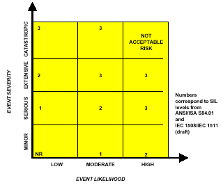
A corporate risk matrix provides control of the SIL assigned for a particular severity and likelihood. During the assessment of the incident severity and likelihood, the available layers of protection must be evaluated and their effect on the incident severity and likelihood must be determined. For risk reduction consideration, the layers of protections must be independent, verifiable, dependable, and designed for the mitigation of the specific risk. An example of the two dimensional Risk matrix is in Fig. 1.
Figure 1. Two dimensional risk matrix
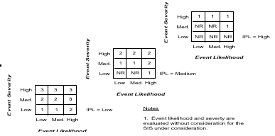
When it is desired that the method provide the capability to formally consider the independent protection layers, a three-dimensional Risk matrix may be used (fig. 2). The assessment of likelihood and severity is done without considering any additional protection layers. The amount of credit taken for the risk reduction inherent in each layer is controlled by the SIL values assigned in the three dimensional matrix. This provides better control in the amount of risk reduction that is assumed with each applied protection layer.
Figure 2. Three dimensional Risk matrix
For this method to be successfully used, the process and its associated risk must be well understood so that the qualitative estimation of the likelihood and severity can be made. The assessment of the likelihood is the most difficult for the assignment team to make, so there should be some general understanding among the assignment team as to frequency of past incidents in the facility or in the general industrial group.
Risk Graph
The international standard IEC 61508 (draft) provides an alternative method to the Risk matrix. It is called a Risk graph and provides a SIL correlation based on four factors:
- consequence (C),
- frequency and exposure time (F),
- possibility of avoiding the hazardous event (P), and
- probability of the unwanted occurrence (W).
This method is a qualitative technique that requires tools to be developed to ensure that the four parameters listed above are properly chosen. It focuses most of the evaluation on an individual person’s risk. The four factors are evaluated from the point of view of a theoretical person being in the incident impact zone. This method is consequence driven, but allows credit for controlling access to the facility. For this method, the likelihood and consequence are determined by considering the independent protection layers during the assessment.
Once these factors are determined, the risk graph is utilized to determine the minimum risk reduction level and associated SIL. As with the Risk matrix, a corporate risk graph should be developed. An example Risk graph is shown in Figure 3.
Figure 3. Example Risk graph
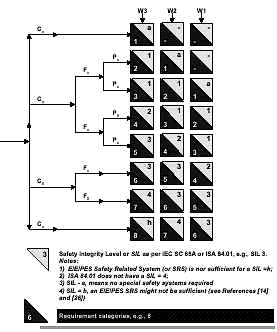
The Risk graph method uses the four parameters: Consequence-C, Frequency of exposure-F, Possibility of escape-P, and Likelihood of event-W. The analysis proceeds with a determination of each of the parameters, in terms of levels shown as subscripted numbers. The Risk graph shown in Fig. 3 has four levels for consequence, two levels for frequency, two levels for possibility of escape, and three levels for likelihood. As the subscripted numbers increase, the perceived hazard is higher. Each of these levels must be carefully defined on a corporate basis for the methodology to be useful. The consequence, C, is not simply defining the incident in terms of loss of containment, fires or chemical releases, as defined in the PHA process. It is examining the incident from the exposed person’s perspective in terms of an injury or fatality. For the example Risk graph shown in Fig. 3, the consequence levels are as follows:
C1 = Minor injury
C2 = Serious permanent injury to one or more persons
C3 = Death to several people
C4 = Very many people killed
In assessing the consequence, the following questions should be evaluated for the incident:
- Is there a potential for injury or fatality?
- Can the exposed person recover?
- Can the exposed person return to normal activities?
- Are the effects acute or chronic?
- Has consequence assessment been performed?
The answers to these questions enable a determination of which of the consequence levels should be chosen.
For the exposure frequency, F, the process unit must be evaluated in terms of the personnel presence and activity in the unit. For the example Risk graph, F1 is chosen for rare to more often exposure in the hazardous zone and F2 is chosen for frequent to permanent exposure in the hazardous zone. The questions for this parameter should address the following:
- Is the process unit remote or in the main personnel traffic area?
- How close are operation and maintenance stations?
- How often is operation’s staff in the vicinity?
- What about support staff, such as maintenance crews or engineering personnel?
- Is this a main travel area for access to other process units?
Possibility of escape, P, can be difficult for the hazards evaluation team to agree upon, because, as engineers and risk assessment people, there is a tendency to want to believe that people can always escape if there are alarms. However, time becomes an important factor in the escape. The example Risk graph uses P1 for possible under certain conditions and P2 for almost impossible. To determine whether it is truly possible or not, the question that should be asked is, "How easy is it to escape from the hazardous area?" Typical issues that should be addressed are as follows:
- Are the escape routes well marked?
- Can personnel in the exposure area readily recognize that a hazardous situation exists?
- Are there alarm sirens?
- Is there time to escape?
- What is the available escape time between alarm and incident?
- Have personnel been through accident scenario training?
- Do the personnel have historical experience with this scenario?
The probability of occurrence, W, is based on the likelihood of the event, which should be evaluated without taking into account any existing safety instrumented systems. The likelihood parameter in the Risk graph is the same as that determined for the Risk matrix. For the example Risk graph, the probability for occurrence is based on the following:
W1 = A slight probability
W2 = A medium probability
W3 = A high probability
The likelihood can be evaluated qualitatively or quantitatively. If a qualitative measure is used, the methodology must define the terms, low, medium, and high.
Quantitative Analysis
The quantitative approach to SIL assignment is the most rigorous technique to utilize. The SIL is assigned by determining the process demand or incident likelihood quantitatively. The potential causes of the incident are modeled using a quantitative risk assessment technique (5), such as that shown in Fig. 4, a fault tree. The quantitative technique is often used when there is very limited historical information about the process, so that the qualitative determination of likelihood is extremely difficult. The method does require a thorough understanding of the potential causes of the event and an estimated probability of each potential cause. Fig. 4 shows some of the potential failures that should be considered.
Figure 4. Quantitative Calculation of Process Demand

To determine the required SIL, the accepted or tolerable risk frequency is divided by the calculated process demand as follows:
![]()
The inverse of this equation has also been used to determine the risk reduction factor (RRF).
![]()
Whichever equation is used, the calculated risk reduction equates to the required safety integrity level.
Corporate mandated choice
The final technique is the least time consuming method, which is one being adopted by many small, specialty chemical plants that do not wish to devote extensive manpower to SIL assignment methodologies. This method recognizes that the greatest increase in cost occurs when the decision is made that the SIL must be higher than SIL 1 (6) . The selection of SIL 2 or SIL 3 forces the SIS design toward device redundancy and diversity. With this recognition, many small companies are taking the approach that "a safety system is a safety system and therefore should be SIL 3". This eliminates the arguments about whether escape is possible, someone will be injured or killed or the impact will be on-site and/or off-site. It saves time in the PHA process, reduces documentation in justifying the SIL choice, and ensures consistency across process units.
Demonstration of methodologies
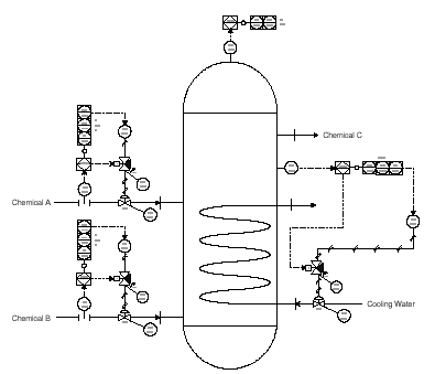
To demonstrate the methodologies described in this paper, a simple example will be provided. The reactor shown in Fig. 5 is utilized in the production of chemical C. Chemical A and chemical B are reacted to produce chemical C. Chemicals A, B, and C are flammable and, under certain conditions, explosive. The reaction is exothermic, so the reactor temperature must be controlled using cooling water. The flow rates of chemical A and chemical B are controlled, because the rate of reactant addition and the ratio of the reactant addition influence the reaction path. A process hazards analysis has documented that, if the flow rates of either chemical A or chemical B exceed certain levels, the reaction will runaway. In addition, the process hazards analysis has shown that if the reaction temperature is not controlled, the reaction path can shift, resulting in a runaway reaction. Both runaway reactions result in volatilization of the reactants and overpressure of the vessel.
Consequence analysis was performed for the various reaction scenarios. It was shown that ignition of the released contents of the vessel would create a pressure wave that would damage a large portion of the facility including the control room.
Figure 5. Simplified P&ID for exothermic reactor example
Modified HAZOP
The modified HAZOP would involve the discussion of the cause, consequence and safeguards for each potential incident. The keyword, More flow, would result in a discussion of the potential for runaway reaction, resulting in the potential overpressure of the vessel and loss of life. The required safeguard would be the installation of a SIS to shutdown the reactor on high reactant flow and on high pressure. The discussion of the likelihood and consequence would result in the team determining that SIL 3 is the best choice.
A similar discussion would occur when the keyword, High temperature, was used, resulting in a high temperature and high pressure initiated SIS. For this example, an action item is shown for the high temperature, "consider providing redundant reactor temperature transmitters." Since the control of the reaction temperature is key for the prevention of overpressure, the integrity of the process control layer should be improved by using redundant transmitters. Table 4 provides an example of the documentation that might be created for the Modified HAZOP.
Table 4. Example modified HAZOP
| Deviation | Cause | Consequence | Safeguards | Action | SIL |
| More Flow | FV-101 fails open | Potential for runaway reaction. Potential to overpressure the reactor with release of flammable/explosive contents. Poetnail for multiple on-site injuires or fatalities | High flow and High Pressure initiate SIS | 3 | |
| High Temperature | TV-103 fails closed or loss of cooling water supply | Same as above | Reactor High Temperature and High Pressure initiate SIS | Consider providing redundant reactor temperature transmitters. | 3 |
Consequence Only
The process hazards analysis identified that the consequence of any ignited release was damage to the control with mulitiple injuires and fatalities. Table 5 shows that this consequence would result in the selection of a SIL 3.
Table 5. Consequence Only Example Table
| SIL | Consequence |
| 3 | Potential for multiple fatalities |
| 2 | Potential for major serious injuries or one fatality |
| 1 | Potential for minor injuries |
Risk Matrix
The information developed during process hazards analysis would be used as the basis for determining the likelihood and severity of the potential incident. Since the high flow rate scenario is caused by a simple loss of process control, the likelihood of this event is high. The documentation has shown that the runaway reaction would result in an overpressure of the vessel, resulting in the potential for severe damage if the released contents are ignited. The severity would be rated as extensive. The two-dimensional matrix shown in Fig. 1 shows that a high likelihood and extensive severity event requires SIL 3. If the three dimensional matrix is used, the other layers of protection would need to be determined. For the runaway reactions involved in this process, the overpressure is developed too quickly to be relieved using a pressure relief valve. Therefore, the presence of the pressure relief valve cannot be used as a mitigating device in the SIL assignment. No acceptable layers of protection were identified during this analysis. Examination of Fig. 2 shows that, at IPL=low and at high severity/high likelihood, the assigned SIL would be SIL 3.
Risk graph
The process hazards analysis indicated the potential for multiple injuries and fatalities, so the consequence is C3. The frequency of exposure is high, F2, since the potential explosion will impact the control room. The Risk graph does not allow the use of possibility of escape at this consequence level (fatalities). The likelihood was determined to be high or W3. From the Risk graph shown in Fig. 3, the required SIL is SIL 4.
Quantitative assessment
A fault tree, such as the one shown in Fig. 5, could be drawn to model the process demand frequency or likelihood for the high temperature incident. This fault tree does not include all of the potential sequences associated with the production of high temperature. For the sake of simplicity, it has been limited to the temperature control loop, cooling water flow, and procedural errors. For completeness, the fault tree would need to be extended to include the effect of the reactant flow on the production of temperature, as well as other direct and indirect causes of high temperature.
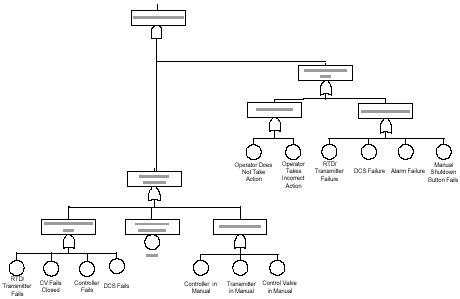
Data is collected from historical evidence and published data sources in order to quantify the fault tree. For this example, the fault tree yielded a process demand frequency of 0.01 per year. The corporate risk tolerance is 0.00001 per year. When the corporate risk tolerance is divided by the process demand frequency, the calculated risk reduction factor is 0.001 or SIL 3.
Conclusion
Unfortunately, there is no easy answer when it comes to assigning SILs. The choice involves examining safety, community, environmental, and economic risks. Most importantly, tools must be developed at the corporate level to ensure that the choice of SIL is consistent with a company’s risk management philosophy and that the assignment method is congruent with the existing characteristics of the corporate risk assessment methodologies. The methods presented are all equally useful in converting PHA data into safety integrity levels (SIL), including Modified HAZOP, Consequence only, Risk matrix, Risk graph, and Quantitative assessment, and Corporate mandated SIL. When choosing a method, there are a number of factors that should be considered:
- What type of method is currently used for corporate risk analysis?
- How complex is the process?
- Is the process well-understood?
- What is the operating experience and knowledge of process dynamics?
- Will the SIL assignment team be consistent from project to project?
Whichever method is chosen, it is necessary for the user to develop procedures and guidelines to ensure that the method is used effectively and consistently.
References
- ANSI/ISA-S84.01-1996 "Application of Safety Instrumented Systems for the Process Industries," Instrument Society of America S84.01 Standard, Research Triangle Park, NC 27709, February 1996.
- IEC 61508, "Functional safety of electrical/electronic/programmable electronic safety related systems," International Electrotechnical Commission, Draft, 1997.
- Guidelines for Hazard Evaluation Procedures, Center for Chemical Process Safety, American Institute of Chemical Engineers, New York, New York, 1992.
- Guidelines for Chemical Process Quantitative Risk Analysis, Center for Chemical Process Safety, American Institute of Chemical Engineers, New York, New York, 1989.
- Adamski, Robert S., "Design Critical Control or Emergency Shutdown Systems for Safety AND Reliability," Automatizacion 96, Panamerican Automation Conference, Caracas, Venezuela, May 1996.
- Windhorst, J.C.A., Strategic Initiative. Nova Chemical, Red Deer, AB, Canada.


