A Practical Overview of Level Continuous Measurement Technologies
Introduction
There are multiple technologies available on the market to measure level. Each and every technology works, when applied appropriately. This paper will discuss the strengths and weaknesses of RF Admittance, Displacers / Floats, Capacitance, Ultrasonic, Radar, Nuclear, Differential Pressure, and Bubbler level measurement technologies. Level measurement for liquids, granulars, slurries and interfaces can be accomplished with several different level technologies. There are over 20 different technologies being offered on the market today. But how do you know which technology to specify for your application? Obviously all technologies have (or had) their place, otherwise companies would not be in business today offering them. The truth is that every technology for level measurement works, when used in the specific circumstances where they have a high probability of success. This paper will discuss the most popular level measurement technologies used in industry, outline their advantages and disadvantages, and tell you where they are best applied. The Application Box Rating Included with the description of each technology is an application box rating for the four categories of level measurement (Liquids, Granulars, Slurries and Interfaces). This gives you an at-a-glance overview of where the technology in question is best used .
|
A green box indicates that this technology is suitable for this category of level measurement. | |
|
A red box indicates that this technology is not practical for this category of level measurement. This does not mean that people have not used this technology for measurement, but just that it is not practical. This could mean that there is excessive maintenance, excessive error, unreliable outputs, or it just simply doesn’t work in this application based on the characteristics of the level measurement. | |
|
A yellow box indicates that this technology can sometimes be applied to this application. But be careful. There are usually special considerations or additional maintenance needed. |
Example: The Application Box Rating below indicates that the technology in question works on liquids. It needs special considerations or additional maintenance when used on slurries, and it is not practical for granulars or interfaces.
| Liquids | Granulars | Slurries | Interfaces |
| EXAMPLE ONLY | |||
Differential Pressure
| Liquids | Granulars | Slurries | Interfaces |
Theory
Perhaps the most frequently used device for the measurement of level is a differential pressure transmitter. Using DP for level is really an inferential measurement. A DP is used to transmit the head pressure that the diaphragm senses due to the height of the material in the vessel multiplied by a density variable.
Advantages
The primary benefit of DP’s is that it can be externally installed or retrofitted to an existing vessel. It can also be isolated safely from the process using block valves for maintenance and testing. There are certain measurements such as total level in separator vessels that due to wide variations in material composition of the upper phase DP is the only viable if not ideal option.
Disadvantages
Typical Differential Pressure Configuration
D/P transmitters are subject to errors due to changes in liquid density. Density variations are caused by temperature changes or change of product. These variations must always be compensated for if accurate measurements are to be made. DP’s are mainly intended for clean liquids and require two vessel penetrations. One is near the bottom of the vessel where leak paths are the cause of the majority of problems. D/P’s should not be used with liquids that solidify as their concentrations increase. An example is paper pulp stock.
Practical Notes
Fluid density must be stable if readings are to be accurate. If liquid density is subject to change a second d/p transmitter is required to measure density and then used to
compensate for any changes. To accommodate the measurement of light slurries, differential pressure transmitters are available with extended diaphragms that fit flush to the side of the vessel. However, if the d/p transmitter diaphragm becomes coated, it may require recalibration, which can be impractical and will add to the "cost of ownership". Frequently, the measuring device is only one consideration in the total installation of the job. Although a D/P transmitter is often less expensive than other types of level sensors, there is usually considerable additional hardware and labour required to make a practical installation. The implementation of a stable, low-pressure leg and 3 / 5 valve manifolds will add considerable cost to the installation.
Displacers / Float
| Liquids | Granulars | Slurries | Interfaces |
Theory
Although float and displacer devices are often similar in appearance they have differing theories of operation. Float devices operate on the buoyancy Principle, as liquid level changes a (predominately) sealed container will, providing its density is lower than that of the liquid, move correspondingly. Displacers work on the Archimedes Principle, when a body is immersed in a fluid it loses weight equal to that of the fluid displaced. By detection of the apparent weight of the immersed displacer, a level measurement can be inferred. When the cross sectional area of the displacer and the density of the liquid is constant, then a unit change in level will result in a reproducible unit change in displacer weight.
Advantages
Both floats and displacers work well with clean liquids and are accurate and adaptable to wide variations in fluid densities. Once commissioned, however, the process fluid measured must maintain its density if repeatability is required, this is particularly true of displacers. Float Switches are available with a glandless design and are capable of fail safe operation in extreme process conditions, unlike displacers, which if the torque tube fails can provide a leak path.
Disadvantages
Displacers are affected by changes in product density since the displacement of the body (its weight loss) is equal to the weight of the fluid displaced. If the specific gravity changes, then the weight of the displaced material changes, thus changing the calibration. This is especially problematic in interface measurements, where both liquids increase or decrease density, while the signal is proportional to the density difference. Because the displacer is emersed in the process fluid it will be vulnerable to
particulate deposition. This will change the displacer mass and the effective displacement causing a calibration shift. Glandless float systems provide more reliable readings under difficult conditions, however in situations of a coating media the moving parts may seize and the unit will no longer function.
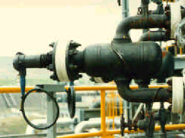
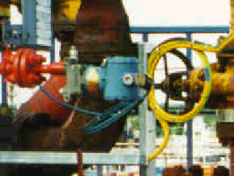
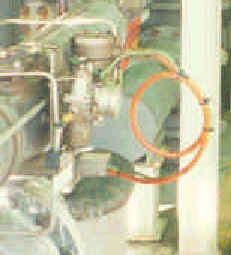
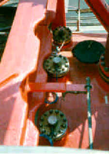
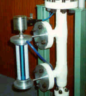
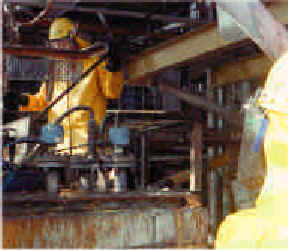
Float Level Switch & chamber on a Cryogenic
Ethylene Application at Exxon, Mossmorran.
Practical Notes
Displacers and floats should only be used for relatively non-viscous, clean fluids and provide optimal performance in switch applications and over for short spans. Spans of up to 12m are possible, but they become prohibitively expensive. Cost of installation for displacers is high and many refineries are now replacing them due to the inaccuracies experienced under process density changes especially on interface duties. High quality float switches still provide reliable and repeatable performance. Even with todays array of level technologies, if a 100% process seal is required under fail conditions for a Cryogenic application the only technique available, other than nucleonic’s, is a magnetically coupled float switch.
Bubblers
| Liquids | Granulars | Slurries | Interfaces |
Typical Bubbler Configuration
Theory
This simple level measurement has a dip tube installed with the open end close to the bottom of the process vessel. A flow of gas, usually air or nitrogen passes through the tube and the resultant air pressure in the tube corresponds to the hydraulic head of the liquid in the vessel. The air pressure in the bubbler tube varies proportionally with the change in head pressure.
Advantages
Simplicity of design and low initial purchase cost are frequently given as advantages of bubblers, but this is somewhat misleading. The system consists of a pipe, an air supply, a pressure transmitter and a differential pressure regulator. The regulator produces the constant gas flow required to prevent calibration changes.
Disadvantages
Calibration is directly affected by changes in product density. It is frequently also necessary to periodically clean this device. The tip of the pipe can collect material from the process, solidify, and plug the hole. Bubblers are not suitable for use in non-vented vessels.
Practical Notes
Instrument air lines should be trace heated if there is a frost risk. Calibration of a bubbler system should be at maximum temperature to avoid overfills. Accuracy depends on a stable air supply and is limited by the regulator, which may be + 10% of full scale. In applications where the purge air is exposed to a hazardous substance, additional steps must be taken to contain any possible contamination.
Ultrasonic / Sonic
| Liquids | Granulars | Slurries | Interfaces |
Theory
Ultrasonic transmitters work on the principle of sending a sound wave from a peizo electric transducer to the contents of the vessel. The device measures the length of time it takes for the reflected sound wave to return to the transducer. A successful measurement depends on reflection from the process material in a straight line back to the transducer.
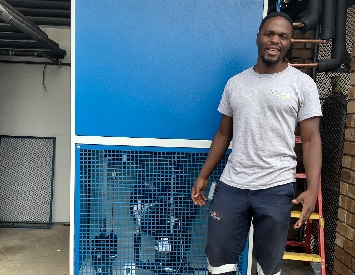
Ultrasonic Level Measurement for bulk storage vessels
Advantages
The main advantages of ultrasonic level instrumentation are that the transducer does not come into contact with the process material, they have no moving parts and a single top of vessel entry makes leaks less probable than fully wetted techniques.
Disadvantages
There are various influences that affect the return signal. Things such as powders, heavy vapors, surface turbulence, foam and even ambient noise can affect the returning signal. Temperature can also be a limiting factor in many process applications. Ultrasonic devices will not operate on vacuum or high pressure applications.
Practical Notes
Successful measurement depends on the transmitter being mounted in the correct position so that the internal structure of the vessel will not interfere with the signal path. To ignore obstructions in the vessel, tank mapping has been developed. Tank mapping lets the operator take a "sonic snapshot" of an empty vessel. The transducer transmits a sound burst and the echo is recorded as a signature of the tank. Any obstructions in the vessel will send an echo and create a profile. Later on, this signature or profile is locked into the ultrasonic unit’s memory so it will not respond to echoes created by these obstructions.
Radar
| Liquids | Granulars | Slurries | Interfaces |
Theory
The two technologies on the market are frequency modulated continuous wave (FMCW) or pulsed wave time of flight. Pulsed Wave systems emit a microwave burst towards the process material, this burst is reflected by the surface of the material and detected by the same sensor which now acts as a receiver. Level is inferred from the time of flight (transmission to reception) of the microwave signal. Microwave "echoes" are evaluated by sampling and building up a historical profile of the echoes. FMCW systems, however, continuously emit a swept frequency signal and distance is inferred from the difference in frequency between the transmit and receive signals at any point in time. FMCW is therefore the only method that is suitable for the high accuracy’s demanded for tank gauging.
FMCW Radar Gauge complete with Data Acuisition Unit
Advantages
This non-contact technology produces highly accurate measurements in storage tanks and some process vessels. Radar is an excellent, but fairly expensive technology (£1k to £5k per measurement) for continuous level measurements. Several manufacturers have reduced the cost/price of the technology with various process radar offerings. These systems do not have the accuracy (and associated cost) of radar used for inventory control. In conclusion, radar can be highly accurate, is immune to most vapours / physical characteristics of the measured media, other than, in some cases, dielectric constant.
Disadvantages
It’s primary disadvantage is cost, which can be justified for tank gauging and inventory control. The pressure ratings on radar antenna are limited and these devices cannot measure interfaces. Pulse radar has difficulty making accurate measurement when the media is in close proximity to the antenna because the time difference between send and return signals is too fast to measure accurately.
Practical Notes
In the case of hydrocarbons, an accurate water bottoms measurement must be made for precise inventory control. Typically, another technology, such as RF Admittance is used to make the interface measurement between water and hydrocarbons. Some installations, such as floating roof tanks, require the installation of a stillpipe. Inconsistencies on the internal surface of the stillpipe can cause erroneous echoes, these can have an adverse effect on the accuracy of some vendor's equipment.
Nuclear
| Liquids | Granulars | Slurries | Interfaces |
Theory
Nucleonic level controls are used for point and continuous measurements, typically where most other technologies are unsuccessful. The radioisotopes used for level measurement emit energy at a fairly constant rate but in random bursts. Gamma radiation, the source generally used for nucleonic level gauging is similar to microwaves or even light (these are also electromagnetic radiation, but of lower energy and longer wavelength). The short wavelength and higher energy of gamma radiation penetrates the vessel wall and process media. A detector on the other side of the vessel measures the radiation field strength and infers the level in the vessel. Different radioisotopes are used, based on the penetrating power needed to "see" the process within the vessel. With single point gauges the radiation provides a simple on/off switching function, whereas with continuous level measurement the percentage of transmission decreases as the level increases.
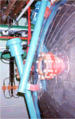
Nucleonic Scintillator Configuration to give linear output of a dished vessel at Cynamid
Advantages
As no penetration of the vessel is needed there are a number of situations that cause nucleonic transmitters to be considered over other technologies. These applications generally involve high temperatures / pressures or where toxic or corrosive materials are within the vessel. Placing the source and / or detector in wells within the vessel can reduce source sizes. An extension of this is to use a moving source within the vessel; this facilitates the unique ability to combine density profiling with accurate tracking of a moving interface.
Disadvantages
It would appear that nucleonic gauges provide a truly universal "fit and forget" level measurement technology. Although when the "cost of ownership" is calculated nuclear level measurement is often more expensive than conventional systems. Hidden costs include initial licensing and periodic surveying. These services are usually provided by external authorities or by the equipment supplier, assuming they have appropriately qualified staff. If no longer required, the nucleonic gauge must be disposed of through appropriately licensed, external organizations, which again can be a costly exercise.
Practical Notes
From a psychological standpoint, the radiation symbol found on these controls is frequently the cause of unfounded concern with uninitiated plant personnel. Plant Management is usually required to ensure that appropriate education is given to any staff likely to be involved with this measurement technology. Source size regulations can often be met in difficult applications by placing the source and / or detector in wells within the vessel if necessary.
Capacitance
| Liquids | Granulars | Slurries | Interfaces |
Theory
As the level rise’s and material begins to cover the sensing element the capacitance within the circuit between the probe and the media (conductive applications) or the probe and the vessel wall (insulating applications) increases. This causes a bridge misbalance, the signal is demodulated (rectified), amplified and the output is increased.
Capacitance Level System in on a Test Rig
Advantages
Capacitance techniques are capable of operation at extremes of temperature and pressure. They work well for materials that won’t leave a coating. Usually only a single tank penetration is required.
Disadvantages
Capacitance systems are intrusive. Have problems with varying dielectric materials and those media’s, that coat the sensing element. Thus users are normally limited to water-like media. Even acids and caustics that don’t appear to coat the sensing element are so conductive that the thin film they leave can cause serious errors in measurement.
Practical Notes
Most users’ realise the limitations of Capacitance level measurement, such as the large errors caused by coatings. This has led to a decrease in the number of these systems in operation. Other technologies such as FMCW radar and in particular RF Admittance have now gained acceptance due to high levels of reliability and accuracy.
RF Admittance
| Liquids | Granulars | Slurries | Interfaces |
Theory
The theory of operation for an RF Admittance level transmitter is similar to that of Capacitance transmitters, but with two important circuit additions. The oscillator buffer and chopper drive circuits permit separate measurement of resistance and capacitance. Since the resistance and capacitance of any coating are of equal magnitude (by physical laws), the error generated by a coating can be measured and subtracted from the total output. The result is an accurate measurement regardless of the amount of coating on the probe.
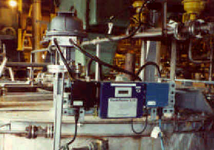
RF Admittance level monitoring of HF Acid & Caustic Soda Levels at BP Grangemouth
Advantages
RF Admittance is next generation capacitance as such it is by far the most versatile technology for continuous level measurement. It can handle a wide range of process conditions anywhere from cryogenics to approximately 850 o C and from vacuum to 10,000 psi pressure. Aside from the electronic circuit technology, sensing element design is very important to handle these process conditions. There are no moving parts to wear, plug, or jam. As with capacitance systems there is only a single tank penetration, usually at the top of the tank, above the actual process level.
Disadvantages
RF admittance is intrusive. Insulating granular measurements require special considerations, such as the moisture range and location of the sensing element to minimize errors caused by probe movement.
Practical Notes
Admittance technology and nucleonic measurement provide the only practical methods for level measurement in coating applications. For insulating materials with changing dielectric constants, the measurement can only be made reliably if the material being measured is homogeneous. A reference sensor is added to monitor the dielectric constant and then compensate the calibration based on this information. Smart RF transmitters are available providing superior levels of stability and accuracy as well as remote communication. Knowledge of the approximate electrical character of the process material is key to optimum system selection and performance.
Summary
The many level technologies available in the market place today all work. If they did not work, companies would not be able to stay in business manufacturing them, and other companies would not be buying them. The important thing to remember is that all technologies work when applied properly. Special consideration must always be given to the principle of operation, and where the limitations of each technology lie. The correct selection of a technology and then the subsequent correct application of the technology will make the level measurement a successful one. Below is a summary list of the general application of the technologies discussed in this paper.
| Liquids | Granulars | Slurries | Interfaces | |
| RF Admittance | ||||
| Ultrasonic | ||||
| Radar | ||||
| Differential Pressure | ||||
| Displacers | ||||
| Bubblers | ||||
| Nuclear |
| Code Key | O.K. | Use Caution | Not practical |
To enable us to provide you with the most accurate and relevant information please contact us with any feedback, both positive and negative, on the content and the method in which you receive forum bulletins. To encourage problem analysis we would particularly like to hear from forum members who have current level measurement problems and those members who have solved difficult applications.